
Rigid Block Model of Tunnel Excavation
Problem Statement
Note
The project file for this example may be viewed/run in PFC.[1] The data files used are shown at the end of this example.
This example simulates tunnel excavation in a deep, highly stressed environment, similar to the case study presented in [Garza-Cruz2014]. Stresses are installed in the initial, zero-porosity Bonded Block Model (BBM) consistent with a tunnel at 1200 m depth, where the lateral stresses are larger than the overburden stress. The Soft-Bond Model contact model provides both the elastic and failure response of the rock mass. The rigid blocks are placed in periodic space in the tunnel advancement direction. In addition, the blocks are coupled with FLAC3D zones in order to create elastic boundaries away from the excavation region. After stress initialization, the tunnel is created by cutting the rigid blocks with fractures. The unbalanced forces on the cut blocks are computed, stored, and applied to the tunnel walls. These forces are subsequently relaxed to simulate tunnel advancement. Fragments are computed at various stages of relaxation. Bonds break initially in tension and shear near the tunnel surface but do not propagate. Shear failures occur at the tunnel corners and near the top of the tunnel, with tensile failures occurring primarily near the lateral walls. At higher levels of relaxation, one observes significant shear failures above and below the tunnel with interspersed tensile failures in all regions around the excavation.
Geometry Creation
The rblock construct command is used to create rigid blocks inside a parallelepiped domain. The resulting tetrahedra form a zero-porosity representation of the rock mass, with specified maximum edge length, that conforms to the boundary of the parallelepiped. A Voronoi tessellation may be advantageous in such BBM models as the algorithm used to create the rigid blocks introduces coherent, pre-existing failure planes that span multiple adjacent blocks, as shown in the figure below. This situation can be mitigated to some degree by assigning a distribution of strengths to the contacts throughout the model; this is the approach taken in this example.
The tunnel geometry is created as the composite of a cylinder and a parallelepiped box. As a result, some manipulation is necessary so that cuts only occur in the blocks at the edge of the tunnel. The geometry polygons are imported as fractures and used to cut the rigid blocks with the rblock cut command. The throughgoing keyword specifies that, should a fracture intersect any portion of a rigid block, the block is cut, while the intersects-box keyword specifies that only rigid blocks intersecting a box are considered for cutting. With these additional keywords the cuts can be performed without additional cuts occurring outside of the tunnel region. The assignment of a group name to the cut blocks allows one to define the intact walls of the tunnel in the rock mass for use later when applying support forces on the tunnel walls. The cut blocks at the tunnel periphery will be termed support blocks.
For a zero-porosity model such as this one, one would expect that the contacts responsible for the elastic response would be located between the faces of adjacent tetrahedra, not located between tetrahedra edges or vertices. For non-bonded contacts, the contact location is defined as the centroid of the volume of overlap. Thus, in order for the face-face contacts to be identified and the contact locations to lie at the centroids of the face-face overlap regions, the rigid blocks are scaled (see the rblock scale command). Should the model be bonded in this state, there would be many edge-edge and vertex-vertex contacts that do not contribute to the elastic response and greatly slow the computation. To effectively remove these contacts during the simulation, the rigid blocks are then rounded while keeping the face locations unchanged (see the rblock erode command). The steps of scaling and eroding the rigid blocks are vital to performant BBM simulations.
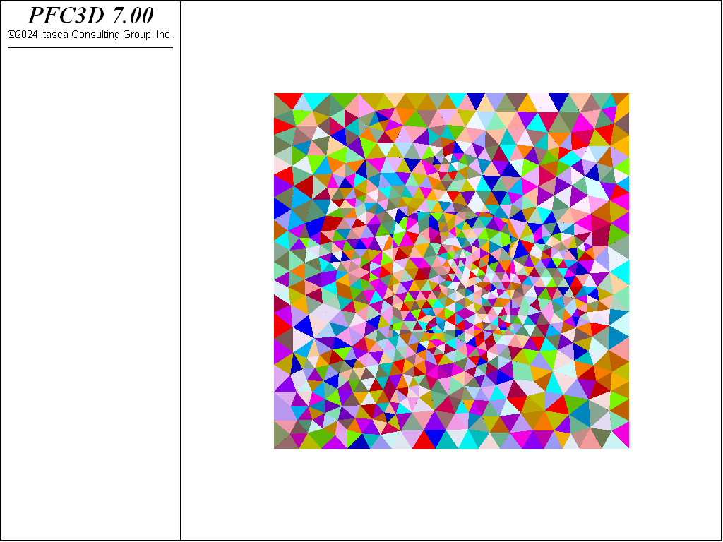
Figure 1: Initial configuration of the rigid blocks after cutting, scaling, and erosion.
Stress Initialization
Zones are created, densified, and attached in a region overlapping the rigid blocks. In order to set the zone stresses appropriately using the zone initialize-stresses overburden command, the zones must be contiguous. To accomplish this, the region overlapping the rigid blocks is initially elastic. Once the stresses in the zones have been initialized, the zones in the overlapping region are assigned the null constitutive model and the zone faces at the boundary of the elastic region are wrapped with walls with the wall-zone create command (see the figure below). The nulled zones are kept so that the zone stresses can be set again using the zone initialize-stresses overburden command, in order for the initial stress state to closely approach the target stress state. The contact forces are set using the contact.force.from.stress intrinsic. Note that an empirically derived coefficient is used to set the contact forces appropriately. These contact forces are not guaranteed to be in equilibrium due to the variable contact orientations and varying number of contacts per rigid block or wall facet. Contacts with negative gap are inhibited meaning that their positions will not be updated and they cannot become active while they continue to be inhibited. The zone stresses are re-assigned to the target values and the model is equilibrated a few times to achieve a closer match to the target initial stress state. The figures below show the target xx-, yy-, and zz-stresses in the zones along with the final values
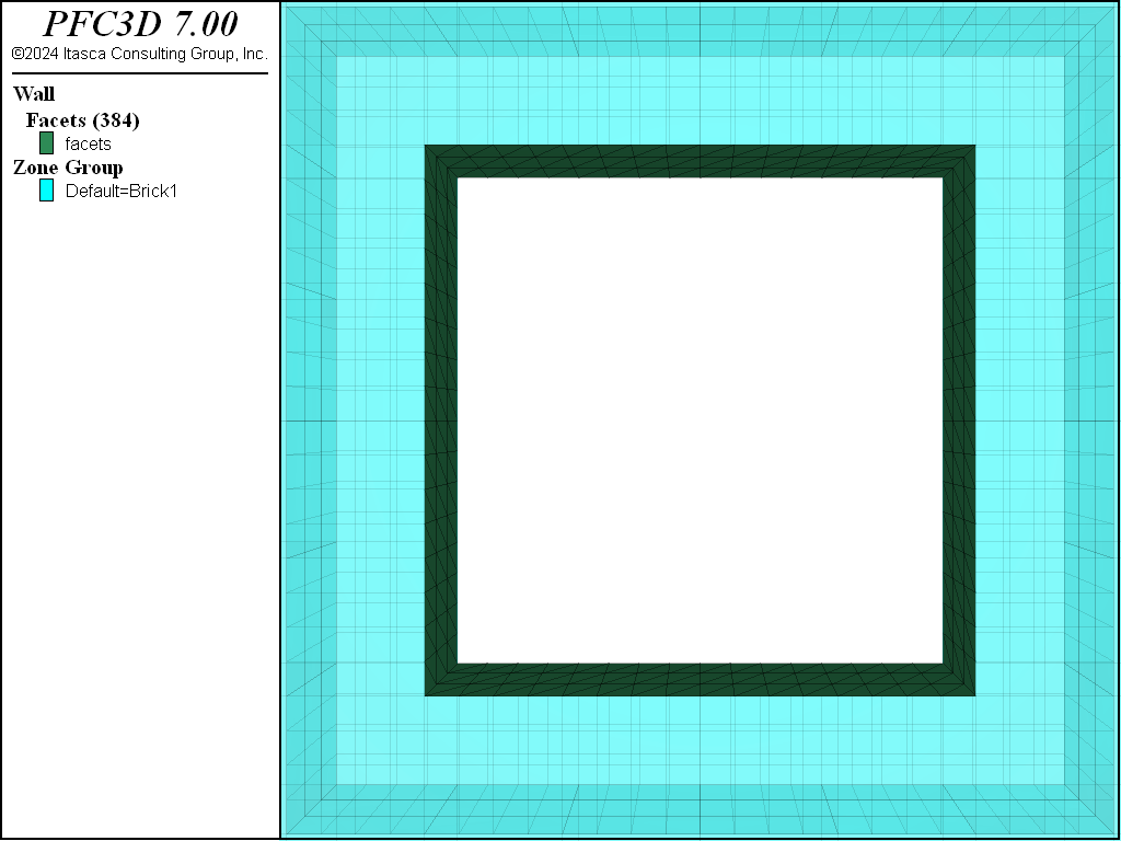
Figure 2: Zones with region wrapped by wall facets.
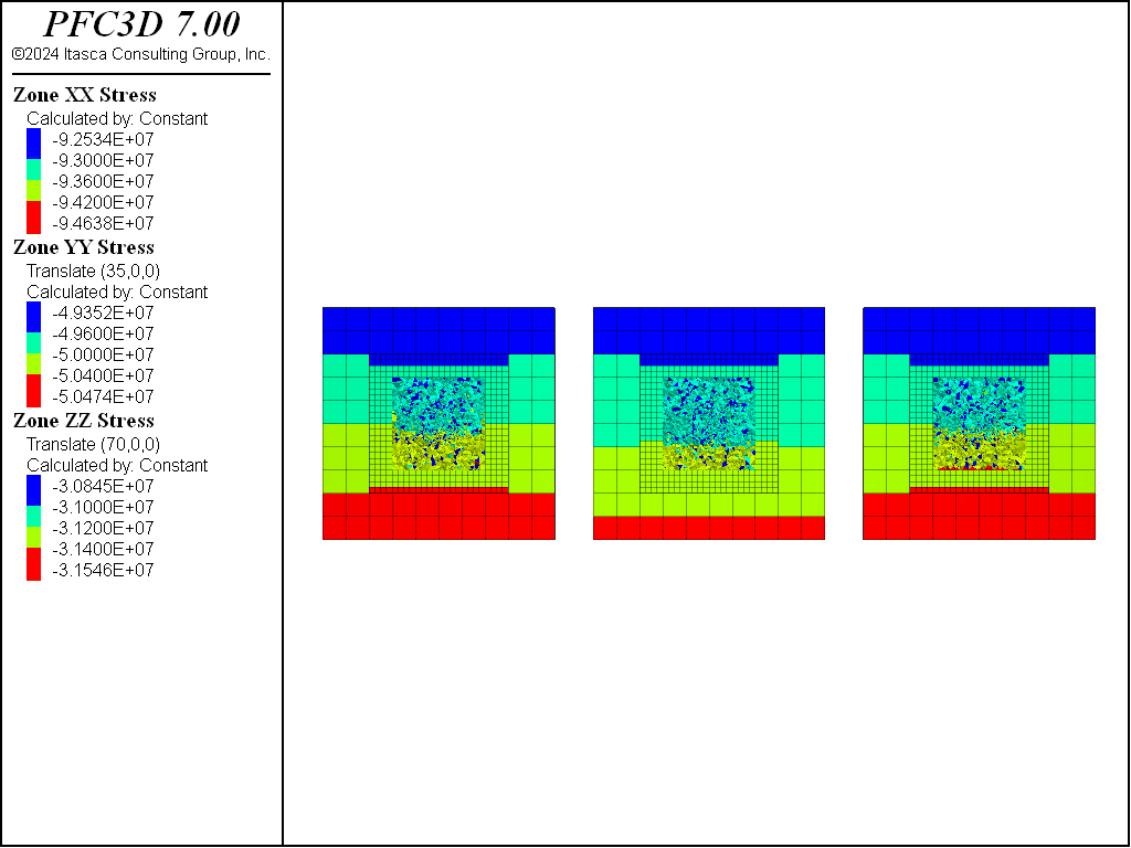
Figure 3: Initial xx-, yy-, and zz- stresses in the zones.
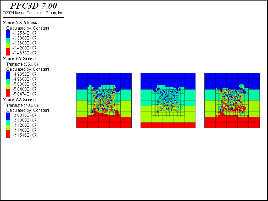
Figure 4: xx-, yy-, and zz- stresses in the zones equilibrated with blocks in the nulled region.
Tunnel Excavation
After the preceding steps the tunnel blocks are deleted, the support blocks are fixed, and the model is equilibrated. The support forces (i.e. the forces required to keep the tunnel from collapsing and near equilibrium) are computed as the negated out-of-balance forces on the support blocks. These support forces are stored as extra variables in each of the support blocks and applied to the support blocks. The support forces will be reduced later in the simulation. Normal distributions of tensile and shear strengths are specified for all rblock-rblock contacts. In this model, should a block become completely unbonded, the inhibition state of all contacts with this rigid block are set to false so that they can become active contacts. This allows for realistic large-strain response while keeping the computational overhead down. In an effort to keep the model in equilibrium while relaxing the support forces, a FISH halt is used that continues to reduce the support forces only when a target average ratio is obtained. In this example the target average ratio of 5e-4 might be larger than desired for certain situations.
Simulation Results
The following figures show the displacement magnitudes where the support forces are reduced to 30, 5, and 0 percent of their initial values. Note the continuity of displacements from the rigid blocks to the zones. Substantial displacement of the roof and floor of the tunnel do not occur until the support forces are relaxed to less than 5 percent of their initial values.
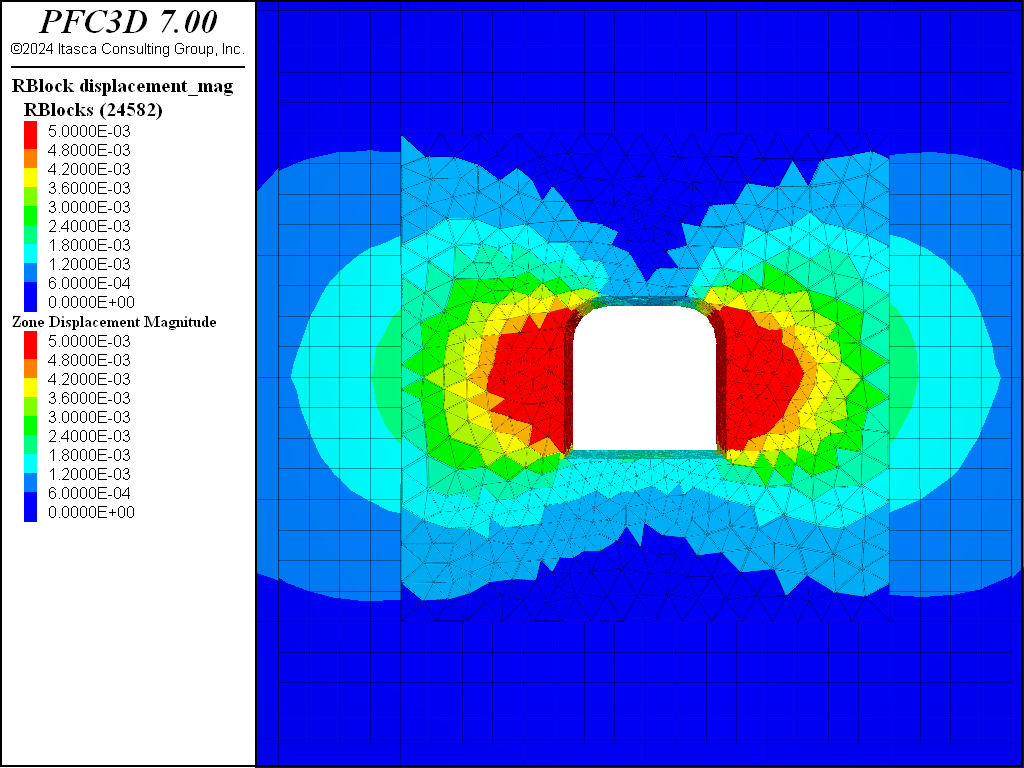
Figure 5: Displacement magnitude with support forces at 30 percent of their initial values.
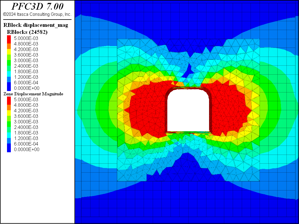
Figure 6: Displacement magnitude with support forces at 5 percent of their initial values.
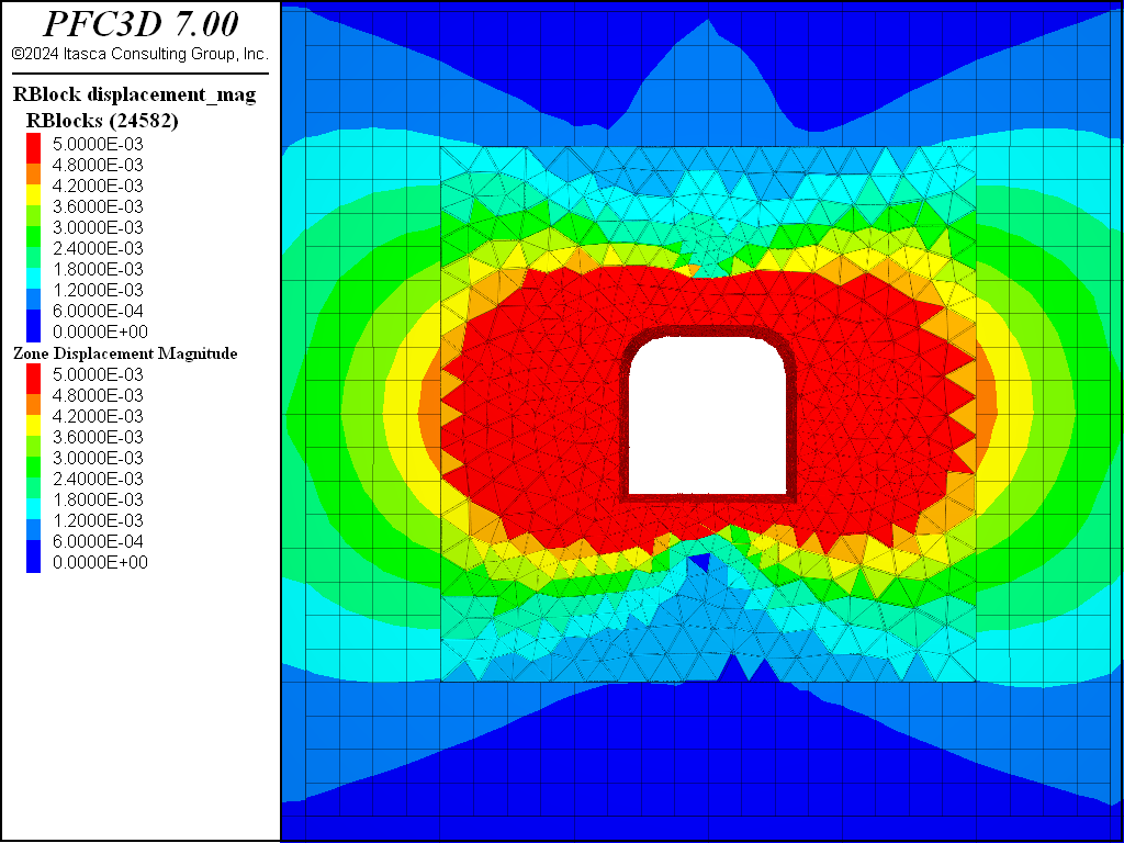
Figure 7: Displacement magnitude with no support forces.
The figures below show the shear and tensile crack evolutions where the support forces are reduced to 30, 5, and 0 percent of their initial values. The cracks are offset and the history of the current percentage of the initial support value is shown. When the support forces are relaxed to 30 percent of their initial values, shear cracks can be observed near the corners of the tunnel floor and near the portion of the roof where the tunnel arches. At 5 percent support force, shear cracks are clearly developing above and below the tunnel. Tensile cracks are also present with some additional tensile cracks near the tunnel walls. With no support forces, arching cracks are clearly visible above and below the tunnel out to about a tunnel radius. Fewer cracks have developed along the tunnel walls.
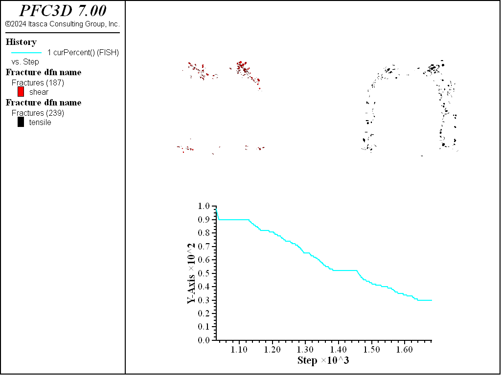
Figure 8: Shear (red) and tensile (black) cracks with support forces at 30 percent of their initial values.
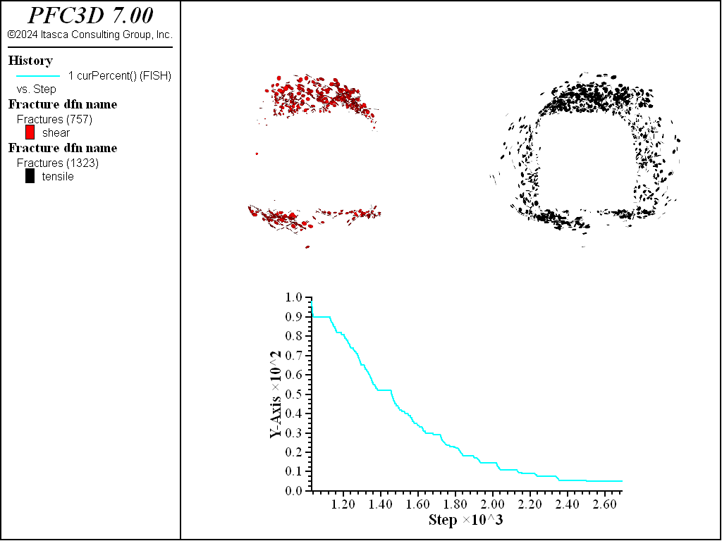
Figure 9: Shear (red) and tensile (black) cracks with support forces at 5 percent of their initial values.
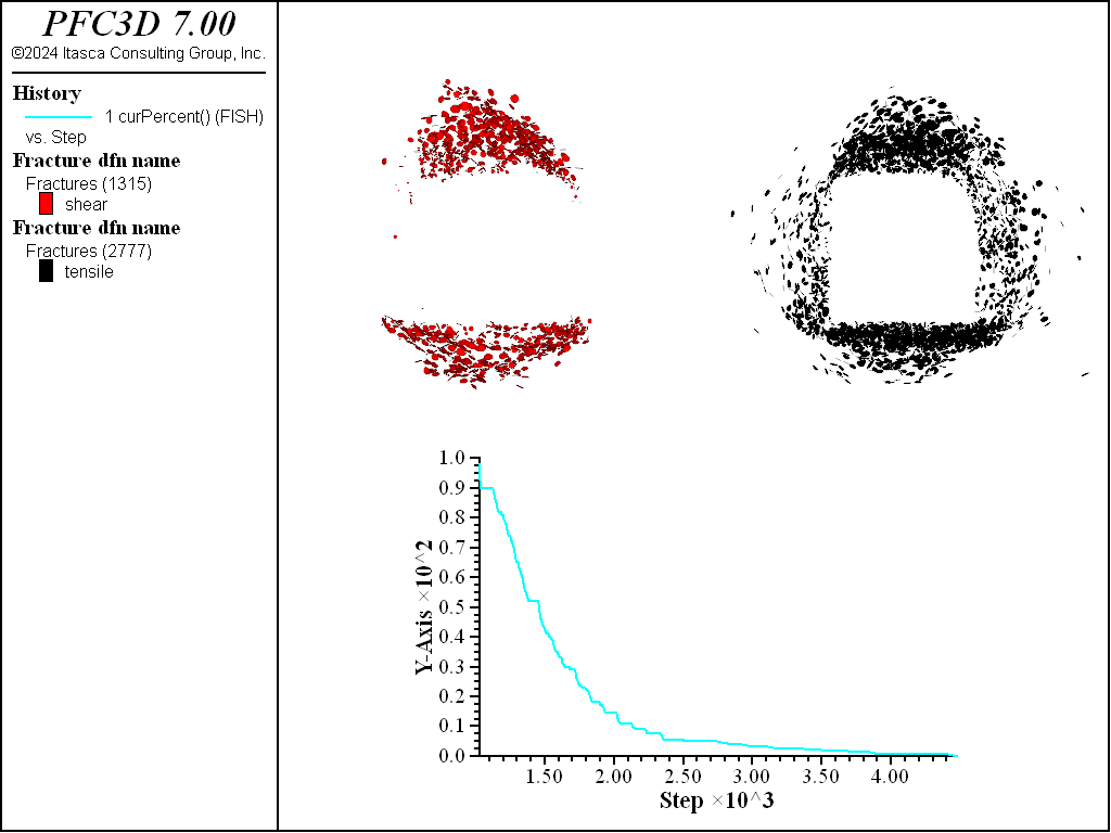
Figure 10: Shear (red) and tensile (black) cracks with no support forces.
Finally the figures below show the fragments where the support forces are reduced to 30, 5, and 0 percent of their initial values. Notice that the fragments develop first above and below the tunnel and then, as the damage increases, the region of fragmentation widens laterally beyond the footprint of the tunnel.
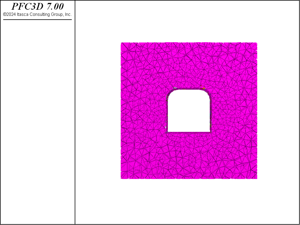
Figure 11: Fragments with support forces at 30 percent of their initial values.
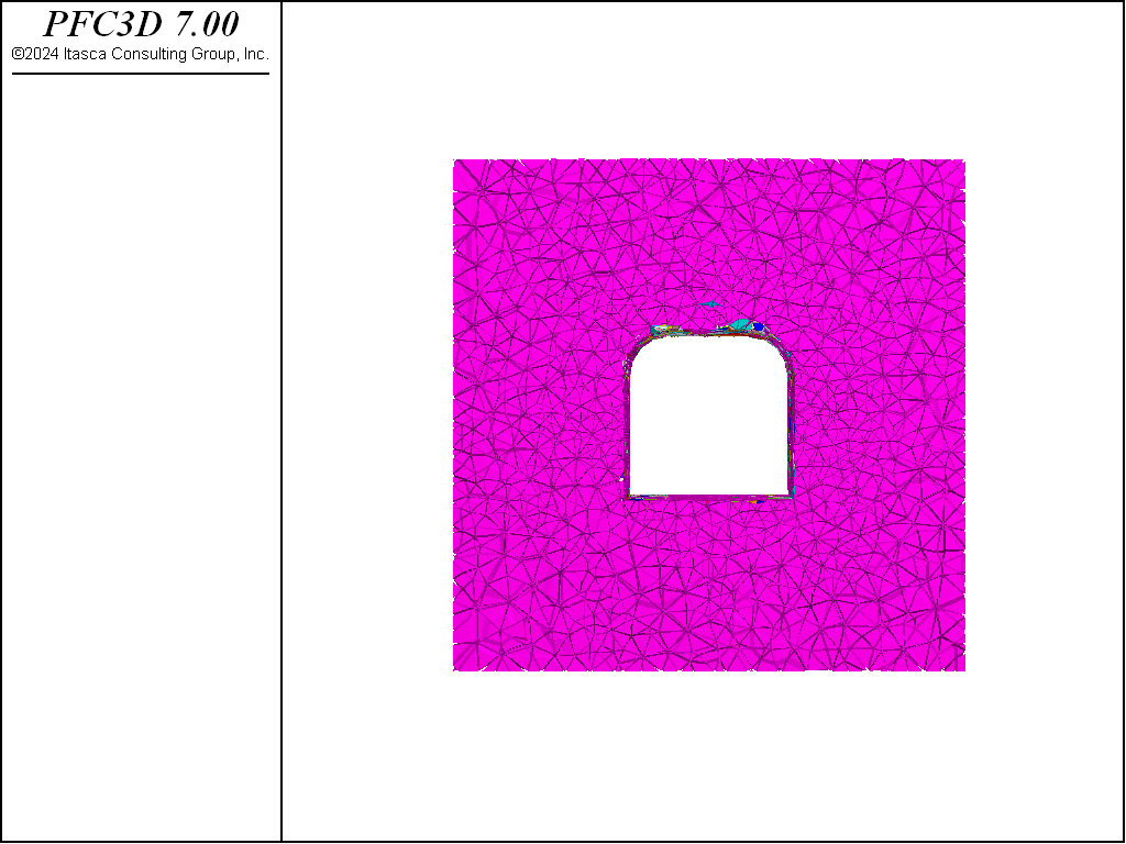
Figure 12: Fragments with support forces at 5 percent of their initial values.
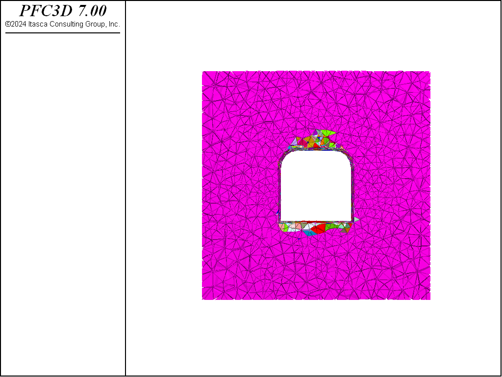
Figure 13: Fragments with no support forces.
References
| [Garza-Cruz2014] | Garza-Cruz, T. and Pierce, M., “A 3DEC Model for Heavily Veined Massive Rock Masses” in Proceedings of the 48th US Rock Mechanics Symposium, ARMA 14-7600, Minneapolis, MN, USA, 2014. |
Endnotes
| [1] | These files may be found in PFC3D under the “examples/tunnelbbm” folder in the Examples dialog ( on the menu). If this entry does not appear, please copy the application data to a new directory. (Use the menu commands . See the “Copy Application Data” section for details.) |
Data Files
geometry.dat
; Create the rigid block geometry. Initially this will just
; be a tetrahedral packing that will later be cut.
model new

; Set the random seed so we get the same results each time
model random 10000

; Specify the domain extent
model domain extent -10 10

; Create a geometry set to construct rigid blocks to fill the
; interior of the set.
geometry set 'blocks'
[lb = vector(-6.,-1.5,-6.)]
[ub = vector(6.,1.5,6.)]
geometry generate box [lb->x] [ub->x] ...
                      [lb->y] [ub->y] ...
                      [lb->z] [ub->z]

; Make geometry nodes throughout the box and give them
; weights (as extra variables) to construct the rblock tetrahedra.
; This will help to eliminate the crystaline mesh using the INTERNAL keyword.
; In this case the sizes of the tets are scaled from the center of the model
[maxEdge = 0.5]
geometry fill [maxEdge]
geometry node extra 1 [maxEdge]
fish define addExtra
    spacing = maxEdge
    std = spacing/2.5
    inMiddle = 0.5
    radius = 4.0
    gs = geom.set.find("blocks")
    loop foreach gn geom.node.list(gs)
        local factor = inMiddle+math.mag(geom.node.pos(gn))/radius*(1-inMiddle)
        val = (math.random.uniform() - 0.5)*2.0*std*factor + spacing*factor
        maxEdge = math.max(maxEdge,val)
        geom.node.extra(gn,1) = val
    endloop
end
[addExtra]
rblock construct from-geometry 'blocks' maximum-edge [maxEdge] internal

; Create the tunnel as a geometry set. The tunnel is composed
; of a cylinder and a box
geometry set 'tunnel-box'
geometry generate box -2 2 -1.5 1.5 -2 2
geometry set 'tunnel-arc'
geometry generate cylinder base 1 -1.5 1  radius 1.0 axis 0 1.0 0 ...
                                          height 3.0 resolution 0.4 cap false
geometry generate cylinder base -1 -1.5 1 radius 1.0 axis 0 1.0 0 ...
                                          height 3.0 resolution 0.4 cap false

; Import the geometry polygons as fractures for cutting
fracture import from-geometry 'tunnel-box'
fracture import from-geometry 'tunnel-arc'

; Cut the rigid blocks, making sure not to cut those not intersected
; by the tunnel boundary
rblock cut fractures 'tunnel-arc' throughgoing group 'supportBlock' ...
                      intersects-box 1 2 -1.5 1.5 1 2               ...
                      sliver-remove false sliver-group 'sliver' slot 'sliver'
rblock cut fractures 'tunnel-arc' throughgoing group 'supportBlock' ...
                      intersects-box -2 -1 -1.5 1.5 1 2             ...
                      sliver-remove false sliver-group 'sliver' slot 'sliver'
rblock cut fractures 'tunnel-box' throughgoing group 'supportBlock' ...
                      intersects-box -1 1 -1.5 1.5 -2 2             ...
                      sliver-remove false sliver-group 'sliver' slot 'sliver'
rblock cut fractures 'tunnel-box' throughgoing group 'supportBlock' ...
                      intersects-box -2 2 -1.5 1.5 -2 1             ...
                      sliver-remove false sliver-group 'sliver' slot 'sliver'

; Put the tunnel blocks in a group - shrink the range to exactly the
; tunnel dimensions
rblock group 'tunnel' range geometry-space 'tunnel-box' ...
                            count odd position-x -1 1
rblock group 'tunnel' range geometry-space 'tunnel-box' ...
                            count odd position-z -2 1
rblock group 'tunnel' range geometry-space 'tunnel-arc' ...
                            count odd

; Scale the rigid blocks so that they overlap initially. This
; is important as the contact position for the bonds is based
; on the original overlap volume. This contact position is
; incrementally updated when bonded.
rblock scale relative 1.01 keep-inertial

; Find the rblocks at the boundary and assign a group. This will
; be used later for fixing the out-of-plane boundaries
rblock group 'boundary' slot 'boundary' ...
              range position-y [lb->y-10] [lb->y] by rblock-vertex union
rblock group 'boundary' slot 'boundary' ...
              range position-y [ub->y] [ub->y+10] by rblock-vertex union

; Remove the geometry set and fractures
geometry delete
fracture delete

; Save the model
model save 'BBM_Geometry'
stress.dat
; Install the initial stress state in the specimen.

; Restore the initial geometry created in the previous step.
model new
;model restore 'BBM_Geometry_Half'
model restore 'BBM_Geometry'

; Specify the material properties. The SimpleBBM example
; can be used to calibrate a specimen.
[density = 2650.0]
[young = 50.0e9]
[poisson = 0.25]
[tensileStrength = 2.e7]
[cohesionFactor = 2.4]
[emod = 7.25e10]

; Elevation used as the top of the model
[topOfModel = -1200.0]

; Set the rigid block damping and density
rblock attribute density [density] damp 0.7

; Use the contact area
rblock contact-resolution update-area true

; Specify the softbond model properties. Initially
; all bonded contacts have infinite strength. This is
; useful when equilibrating the model.
contact cmat default model softbond method deformability emod [emod] ...
                           kratio 2.0 ...
                           property sb_ten 1e100 sb_coh 1e100 ...
                           sb_fa 30.0 fric 0.5 sb_mode 1

; Create zones
zone create brick size 10 3 10  point 0 -15 -1.5 -15  point 1 15 -1.5 -15  ...
                                point 2 -15  1.5 -15  point 3 -15 -1.5 15

; Densify the zones near to the rigid blocks
zone densify local maximum-length (1,1,1) range position-z -9 9 position-x -9 9

; Assign the zone material properties
zone cmodel assign elastic
zone property density [density] young [young] poisson [poisson]

; Turn on gravity
model gravity 0 0 -9.8

; Initialize zone stresses
zone initialize-stresses overburden [(topOfModel+15.0)*density*9.81] ...
                         ratio 3.0 1.6 direction-x 1.0 0 0

; Group the zones that will be nulled where the rigid blocks reside
zone group 'nullZones' range position-z -6 6 position-x -6 6
zone cmodel assign null range group 'nullZones'

; Attach - necessary as the zones have been densified
zone attach by-face

; Wrap the null zone edges with wall facets
wall-zone create name 'wrapper' range position-x -6.5 6.5 ...
                                      position-z -6.5 6.5 position-y -1.4 1.4

; Have the stiffness be computed
wall-zone compute-stiffness true

; Identify gridpoints for roller boundary conditions
zone gridpoint group 'z' slot 'boundary-z' range position-z -100 -15 ...
                                                 position-z 15 100 union
zone gridpoint group 'x' slot 'boundary-x' range position-x -100 -15 ...
                                                 position-x 15 100 union
zone gridpoint group 'y' slot 'boundary-y' range position-y -100 -1.5 ...
                                                 position-y 1.5 100 union

; Fix the rigid blocks and zones
rblock fix velocity spin
zone gridpoint fix velocity

; Create the contacts and scale the timestep
model mechanical timestep scale
model large-strain on
model cyc 1

; Ensure that the contact areas are unchanged
contact method area

; Inhibit contacts, checking if they should be reactivated every
; 1000 cycles
rblock contact-resolution inhibit-contacts inhibit-interval 1000

; Bond the contacts where rigid blocks overlap
contact method bond range contact active

; Now erode the rigid blocks, removing edge-edge and vertex-vertex.
; This is important as it will greatly increase computational efficiency.
; These contacts do not contribute to the response of the bonded material.
rblock erode relative 0.1 skip-errors

; Specify the stress
rblock tractions overburden [(topOfModel+12.0)*density*9.81] ...
                         ratio 3.0 1.6 direction-x 1.0 0 0 contact-active false

; Free the rigid blocks and zones
rblock free velocity spin
zone gridpoint free velocity

; Fix the boundary rblocks and zones
rblock fix velocity-y range group 'boundary'
zone gridpoint fix velocity-z range group 'z' slot 'boundary-z'
zone gridpoint fix velocity-x range group 'x' slot 'boundary-x'
zone gridpoint fix velocity-y range group 'y' slot 'boundary-y'

; Save the initial state
model save 'BBM_Initial'

; Solve to an average ratio
model solve ratio-average 1e-5

; Get closer to the target stress state
fish define reachTarget
    loop local i(1,2)
        command
            zone cmodel assign elastic range group 'nullZones'
            zone initialize-stresses overburden ...
                                     [(topOfModel+15.0)*density*9.81] ...
                                     ratio 3.0 1.6 direction-x 1.0 0 0
            zone cmodel assign null range group 'nullZones'
model cycle 1
model solve ratio-average 1e-5
        endcommand
    endloop
end
[reachTarget]

; Save the equilibrated model
model save 'BBM_Equil'
excavate.dat
; Cut out the tunnel
model new

; Restore the equilibrated model
model restore 'BBM_Equil'

; Delete the tunnel rigid blocks
rblock delete range group 'tunnel'

; Delete the slivers
rblock delete range group 'sliver' slot 'sliver'

; Reset the velocities of the blocks and zones
model calm

[fixMap = rblock.groupmap('supportBlock')]

; Fix all dof of the the support blocks
rblock fix velocity spin range group 'supportBlock'

; Get the model back into equilibrium
model cycle 1
model solve ratio-average 1e-5

; For each rigid block in the apply group we need to set the
; applied force and also, if it isn't bonded to anything, need
; to activate all of the contacts
fish define computeSupportForce
    loop foreach local rb fixMap
        if rblock.isbonded(rb) == false
            loop foreach local con rblock.contactmap.all(rb)
                contact.inhibit(con) = false
            endloop
        endif
        rblock.force.app(rb) = vector(0,0,0)
        rblock.force.app(rb) = -1.0 * rblock.force.unbal(rb)
        rblock.extra(rb,1) = rblock.force.app(rb)
    endloop
end
[computeSupportForce]

; Free the support blocks and equilibrate
rblock free velocity spin range group 'supportBlock'
model cycle 1
model solve ratio-average 1e-5

; Reset the displacement of the blocks and zones
rblock attribute displacement 0 0 0
zone gridpoint initialize displacement 0 0 0

; FISH function used to define the tensile and shear strength. It
; returns a non-negative value from a normal distribution with
; given mean and standard deviation. It must take a contact point
; as the first argument.
fish define normalDist(c,mean,sdev)
    loop while true
        local val = mean + (math.random.gauss * sdev)
            if val >= 0.0 then
                normalDist = val
                exit
            endif
    endloop
end

; Assign the normal distribution of tensile and shear strengths
contact property sb_ten normalDist [tensileStrength] [tensileStrength/5.0] ...
                                    range contact type 'rblock-rblock' ...
                                    contact active
contact property sb_coh normalDist [tensileStrength * cohesionFactor] ...
                                    [(tensileStrength*cohesionFactor)/5.0] ...
                                    range contact type 'rblock-rblock' ...
                                    contact active

; Create a DFN for crack tracking
[shearNetwork = dfn.create("shear")]
[tensileNetwork = dfn.create("tensile")]
[diskArray = array.create(5)]
[diskArray(1) = "disk"]
[trackCracks = false]

; Define a fish callback to track bond breakages.
fish define onBondBreak(arr)
    con = arr(1)
    if trackCracks == true
        ; Do not track cracks that happen in the periodic space
        if math.mag(contact.offset(con)) == 0.0
            local mode = arr(2)
            diskArray(2) = contact.pos(con)
            diskArray(3) = math.sqrt(contact.prop(con,'sb_area') / math.pi)
            local norm = contact.normal(con)
            diskArray(4) = math.dip.from.normal(norm)/math.degrad
            diskArray(5) = math.ddir.from.normal(norm)/math.degrad
            if diskArray(5) < 0.0
                diskArray(5) = 360.0+diskArray(5)
            endif
            if mode == 1
                fracture.create(tensileNetwork,diskArray)
            else
                fracture.create(shearNetwork,diskArray)
            endif
        endif
    endif
end

; Add this callback to the bond_break event
fish callback add onBondBreak event bond_break

; Reset the velocities of the blocks and zones
model calm

; Solve to equilibrium with the correct tensile and shear
; strengths installed
model cycle 1
model solve ratio-average 1e-5

; Reset the block and zone displacements for the last time
rblock attribute displacement 0 0 0
zone gridpoint initialize displacement 0 0 0

; Start tracking cracks
[trackCracks = true]

; Save the model
model save 'BBM_Tunnel'


; FISH halt used to relax the support force. Basically you specify
; the current percentage, final percentage, increment to reduce the
; percentage by, and the target average ratio. As cycling continues
; the halt checks for the average ratio smaller than the target value.
; If not smaller then continue to cycle otherwise reduce the current
; percentage by the increment. This reduction continues until the final
; percentage is achieved.
[curPercent = 100]
[endPercent = 30]
[increment = 1]
[targetAveRatio = 5.e-4]
fish define halt
    halt = 0
    currentAveRatio = math.max(zone.mech.ratio.avg,rblock.mech.ratio.avg)
    if curPercent <= endPercent
        if currentAveRatio <= targetAveRatio
            halt = 1
        endif
        exit
    endif
    if currentAveRatio <= targetAveRatio
        curPercent = math.max(0.0,float(curPercent) - float(increment))
        loop foreach local rb fixMap
            rblock.force.app(rb) = rblock.extra(rb,1) * curPercent / 100.0
        endloop
    endif
end

; Record the current percentage as a history and solve
fish history name '1' curPercent
history interval 1
model solve fish-halt halt

; Save the model where the support stress is ramped to 30 percent of the
; original value
model save 'BBM_30_Percent'

; End at 5 percent with an increment of 0.5 percent, solve, and save the model
; where the support stress is ramped to 5 percent of the original value
[endPercent = 5]
[increment = 0.5]
model solve fish-halt halt
model save 'BBM_5_Percent'

; End at 0 percent with an increment of 0.01 percent, solve, and save the
; model where the support stress is ramped to 0 percent of the original value
[endPercent = 0]
[increment = 0.01]
model solve fish-halt halt
model save 'BBM_0_Percent'

; Register the rigid block contacts and compute the fragments
fragment register rblock-rblock persist off
fragment compute
Endnotes
| [2] | To view this project in PFC, use the program menu.
⮡ PFC |
| Was this helpful? ... | PFC © 2021, Itasca | Updated: Feb 25, 2024 |