Background Images / Geometric Data
An extrusion set accepts two types of background images: bitmaps (BMP, JPG, PNG, etc.) and geometric data sets (DXF, GEOM, STL). Either may be used as a guide to construct the extrusion. The difference is that a bitmap is, effectively, a picture, whereas a geometric data set contains the numeric information associated with the image and that data may be used to automatically create extruder edges conforming to the background geometry (see Creating Edges from Background Geometry in Edge Tools). Note that a single extrusion set will accept one bitmap and one geometric data set only.
Import a Background Image
Press the Import button ( ) on the toolbar to import a background image into an extrusion set. The accepted file types are
- Image files (*.bmp *.pbm *.pgm *.png *.ppm *.xbm *.xpm)
- DXF files (*.dxf)
- Geom files (*.geom)
- STL files (*.stl)
When a file is opened, the image will be automatically placed in the construction view.
Select a Background Image
To select a background image, double-click anywhere within its limits using the select tool. When it is selected, it will appear with handle points around it:
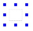
Figure 1: The handle points as they appear when an image is selected
An image may also be selected by right-clicking it and choosing the Select Background Image menu command.
Deselect an Image
- Once an image is selected, it may be deselected by:
- pressing Esc key,
- clicking anywhere outside the bounds of the bitmap rectangle,
- selecting a different tool from the toolbar,
- right-click the selected image and choose Exit Mode from the context menu.
Move a Background Image
Select the image per above, then drag from within the image (not on one of the handle points).
Resize a Background Image
Select the image per above, then drag a handle point. Aspect ratio is always maintained when resizing, regardless of which handle point is used in the operation. When the mouse is positioned over a handle point so that it may be used to resize, that point will be highlighted in cyan. The resize operation will take the point opposite the chosen handle point as an anchor (that is, the fixed point of reference) for the resize operation. See also Pin a Background Image below.
Pin a Background Bitmap Image
A point of reference for resizing — a pin — may be set by first selecting the background image and then right-clicking it and selecting Set Pin. This will change the mouse cursor to the pin ( ), which can be placed anywhere within the background image by clicking at the desired point. When setting the pin, it is useful to observe the position of the cursor in the status bar. After clicking to set the pin, the image may be resized using it as the anchor.
Using the pin can be part of a process for positioning and sizing a bitmap image which may serve as a reference for your model. The animated figure below shows an example of such process. In this example, the coordinates of the lower left corner, bench floor width and elevation are known which allows positioning of extruder points at these locations. After that the image is moved and scaled to conform to these locations, and extruder edges are created along the edges of the image.
Figure 2: Building extruder edges from background bitmap image while using a pin
Note that when the image is de-selected, the pin is removed as well.
Rotate a Background Image
To rotate the image, select it and double-click on it again. A rotation circle, as shown below, will indicate that the image can be rotated.
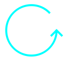
Figure 3: The rotation symbol indicates that the image can be rotated
While in this mode, press the mouse left button to grab the image and move the mouse to rotate the image. The rotation angle (from horizontal) can also be set in the Object Properties control set.
Cycling the Edit Modes
Repeatedly double-clicking the image will cycle through these three states: select for re-sizing/repositioning, select for rotation, and deselect.
Snap-To Behavior on Background Geometry
While using the point-edge tool, place the mouse over a geometric data set to highlight the edges and to snap to them. When the mouse is placed over or near a vertex where multiple edges join, they all will be highlighted; clicking the mouse will place an extruder point at the node location.
Figure 4: Putting the point-edge tool over any vertex of a geometric data set highlights all background edges joining at the vertex and allows snapping to the vertex.
Holding the Shift key down while using the point-edge tool will suspend snap-to behavior. Holding the Control key down while adding an edge will cause the edge to snap to an angle primarily and to geometric data if highlighted.
Note that snap-to behavior is not available on a pixel-based (bitmap) background image.
Selection With Two Images in the Extrusion
An extrusion may contain one pixel-based (bitmap) image and one data-based (geometry) data set. In the event that these overlap, and you double-click within an area of overlap, the order of edit states will be:
- select the bitmap for resizing/repositioning
- select the bitmap for rotation
- select the geometry for resizing/repositioning
- select the geometry for rotation
- de-select (remove selection)
| Was this helpful? ... | 3DEC © 2019, Itasca | Updated: Feb 25, 2024 |