Exporting 3DEC models
3DEC blocks and zones can be exported to a file for import into another 3DEC model (see Importing and Merging). It is also possible to export 3DEC models to be imported into other Itasca programs.
Exporting to FLAC3D
The block to-flac3d command can be used to export 3DEC zones and joints to a FLAC3D grid file. 3DEC zones will make FLAC3D zones, and 3DEC joints will make FLAC3D interfaces. FLAC3D zones will be assigned group names and slots equal to block groups in 3DEC.
Interfaces are not part of the FLAC3D grid file. Therefore along with the grid file, a FLAC3D data file is exported. This file creates interfaces from zone faces. Interfaces will be assigned group names equal to the joint set id prepended by “i”. Subsequent property assignment to interfaces that form different joint sets is simplified through use of the group range element. The data file also automatically merges gridpoints between joined 3DEC blocks.
An example is shown below. This is a variation on the Quick Start Tutorial. Keep in mind that blocks in 3DEC must be zoned if they will be used to create a FLAC3D model.
The file simple_wedge_3dec.dat shows the 3DEC data file that creates a wedge in a laminated rock. When the block to-flac3d command is given, a FLAC3D data file called “3dec.dat” is created along with a grid file called “3dec.f3grid”. The name of the data file and the gridfile can be supplied using the keyword filename. The output file can also be made binary by using the binary keyword.
The resulting FLAC3D data file is shown in 3dec.dat. The first line imports the grid. The second line merges gridpoints for joined blocks. In more realisitic models there will be many of these zone gridpoint merge commands. Subsequent lines create interfaces from zone faces. Finally, a FISH function at the end assigns group names to the interfaces.
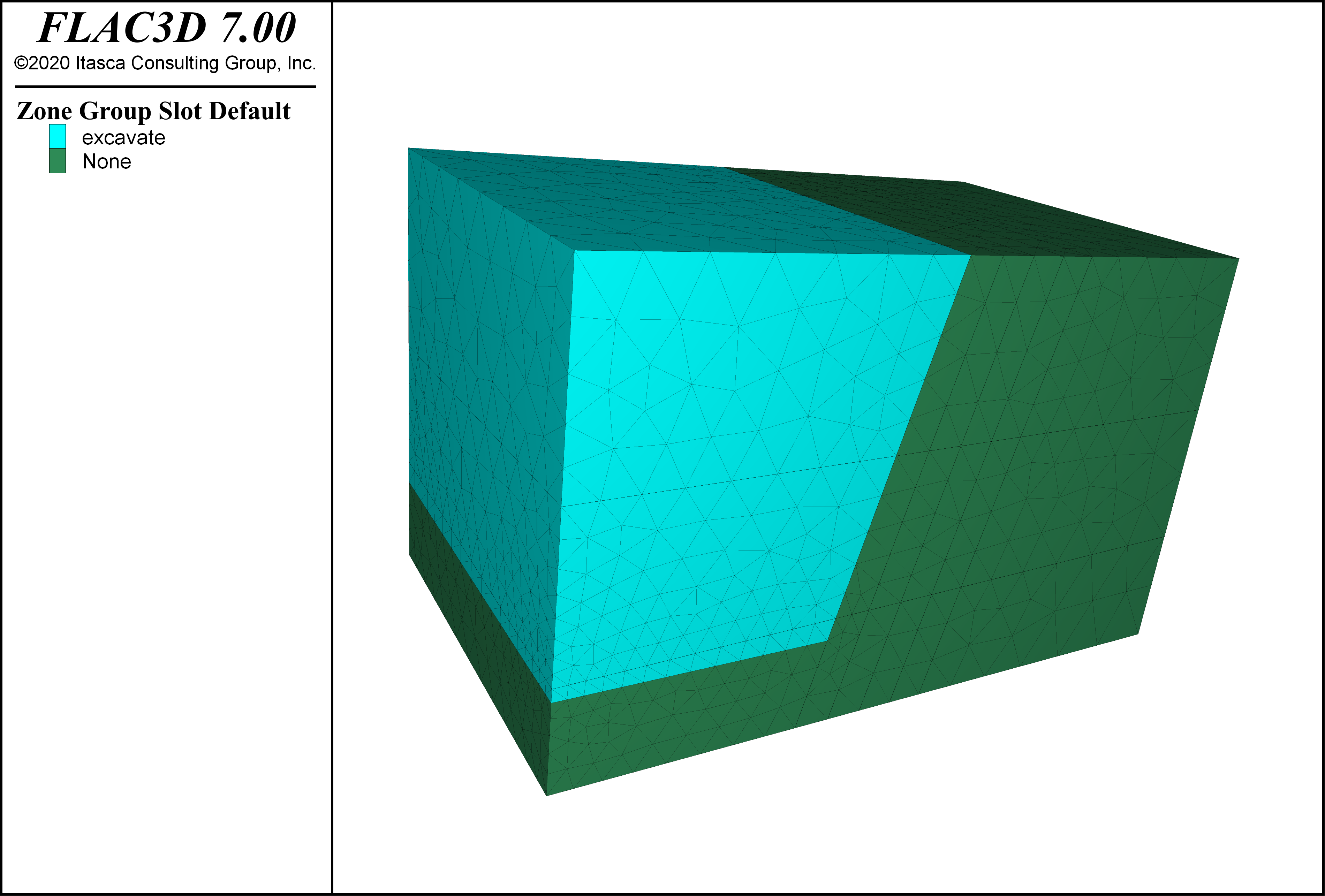
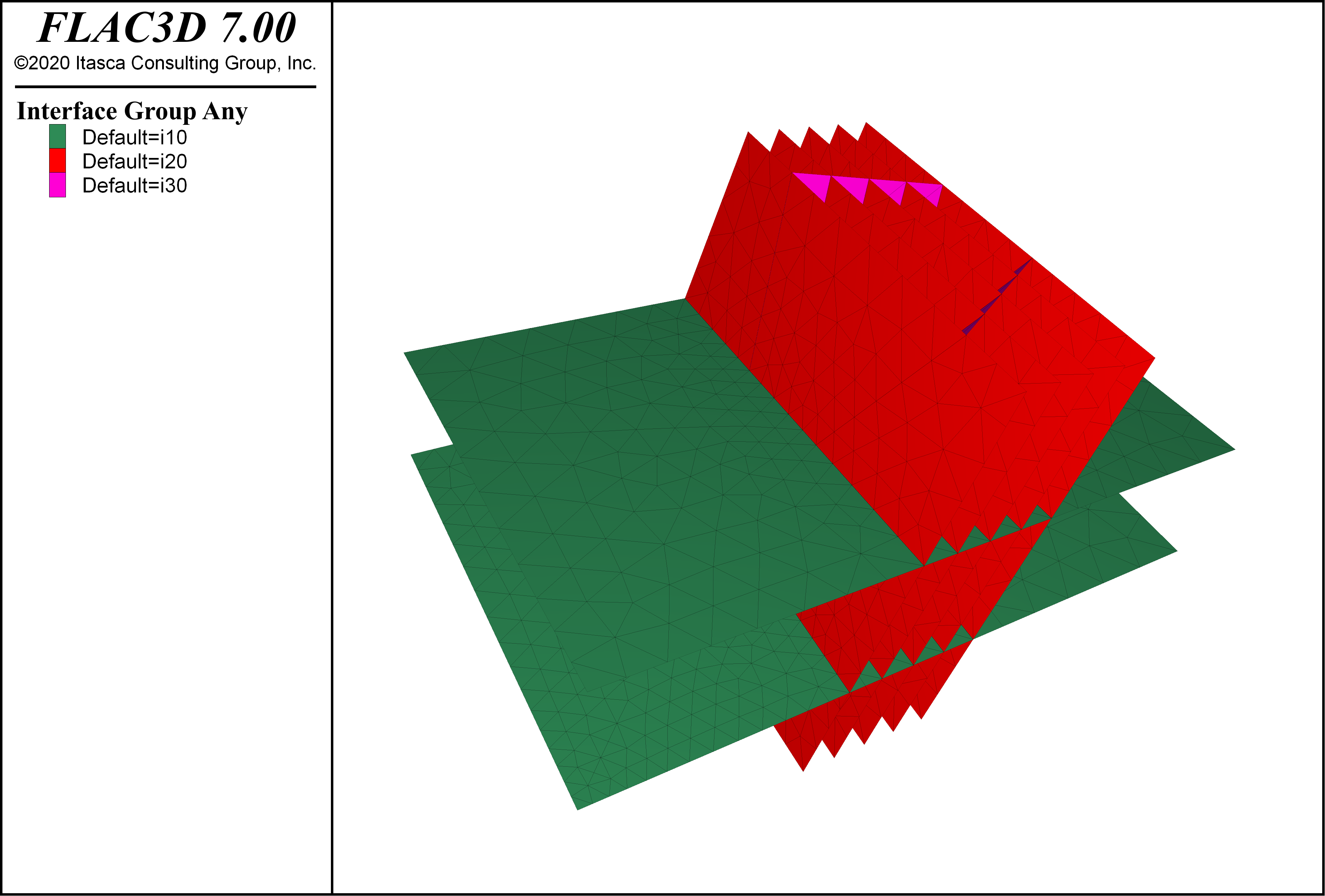
The zones and interfaces resulting from running the FLAC3D data file are shown in Figure 1 and Figure 2.
simple_wedge_3dec.dat
model new
model random 10000
;
block create brick (0,80) (0,50) (0,50)
;
; create sub-horizontal joints
block cut joint-set dip 2.5 dip-direction 235 origin 30,0,12.5 jointset-id 10
block cut joint-set dip 2.5 dip-direction 315 origin 35,0,30 jointset-id 10
;
; create steeply dipping foliations
block cut joint-set dip 76 dip-direction 270 spacing 4 num 5 ...
                    origin 38,0,12.5 jointset-id 20
;
; create base and identify region to be excavated
block hide range position-x 30,80
block cut joint-set dip 0 dip-direction 0 origin 0,0,10 join
block hide range position-z 0,10
block group 'excavate'
block hide off

; cut wedge
block hide range position-z 0,10
block hide range position-x 55,80
block hide range position-x 0,30
block cut joint-set dip 70 dip-direction 200 origin 0,35,0 jointset-id 30
block cut joint-set dip 60 dip-direction 330 origin 50,15,50 jointset-id 30
block hide off

; zone it
block zone generate-new

; export to FLAC3D
block to-flac3d

; export to PFC (blocks)
block to-pfc

; export to UDEC (blocks)
block to-udec origin 0,25,0 dip 90 dip-direction 0
3dec.dat
zone import '3dec.f3grid'
zone gridpoint merge tol-rel 1e-6 range group 'b19' slot 'master'
===========================================================
zone interface 'i10_1' create by-face range group '10_1'
zone interface 'i20_1' create by-face range group '20_1'
zone interface 'i20_2' create by-face range group '20_2'
zone interface 'i20_3' create by-face range group '20_3'
zone interface 'i20_4' create by-face range group '20_4'
zone interface 'i20_5' create by-face range group '20_5'
zone interface 'i30_1' create by-face range group '30_1'
===========================================================
fish define interface_group
  loop foreach ip interface.list
    local int_name = interface.name(ip)
    local position = string.find(int_name, '_')
    local ip_grp = int_name(1, position - 1)
    interface.group(ip) = ip_grp
  end_loop
end
[interface_group]

Figure 1: FLAC3D zones created from exporting a 3DEC model.

Figure 2: FLAC3D interfaces created from exporting a 3DEC model.
Two other examples are provided that can be run in FLAC3D in demonstration mode. These reproduce the falling wedge and sliding wedge verification problems. To run them, start FLAC3D and go to and choose “3DEC/ ExampleApplications/ Users_Guide / Convert”.
Exporting to PFC
3DEC blocks or zones can be converted to PFC rigid blocks using the command block to-pfc. When the command is given, a PFC data file is produced that defines an assembly of PFC rigid blocks. By default, 3DEC blocks are converted to PFC rigid blocks. If the keyword by-zone is specified, the tetrahedral zones are exported. The information about groups names and slots is kept in PFC meshes. The 3DEC joints are not exported.
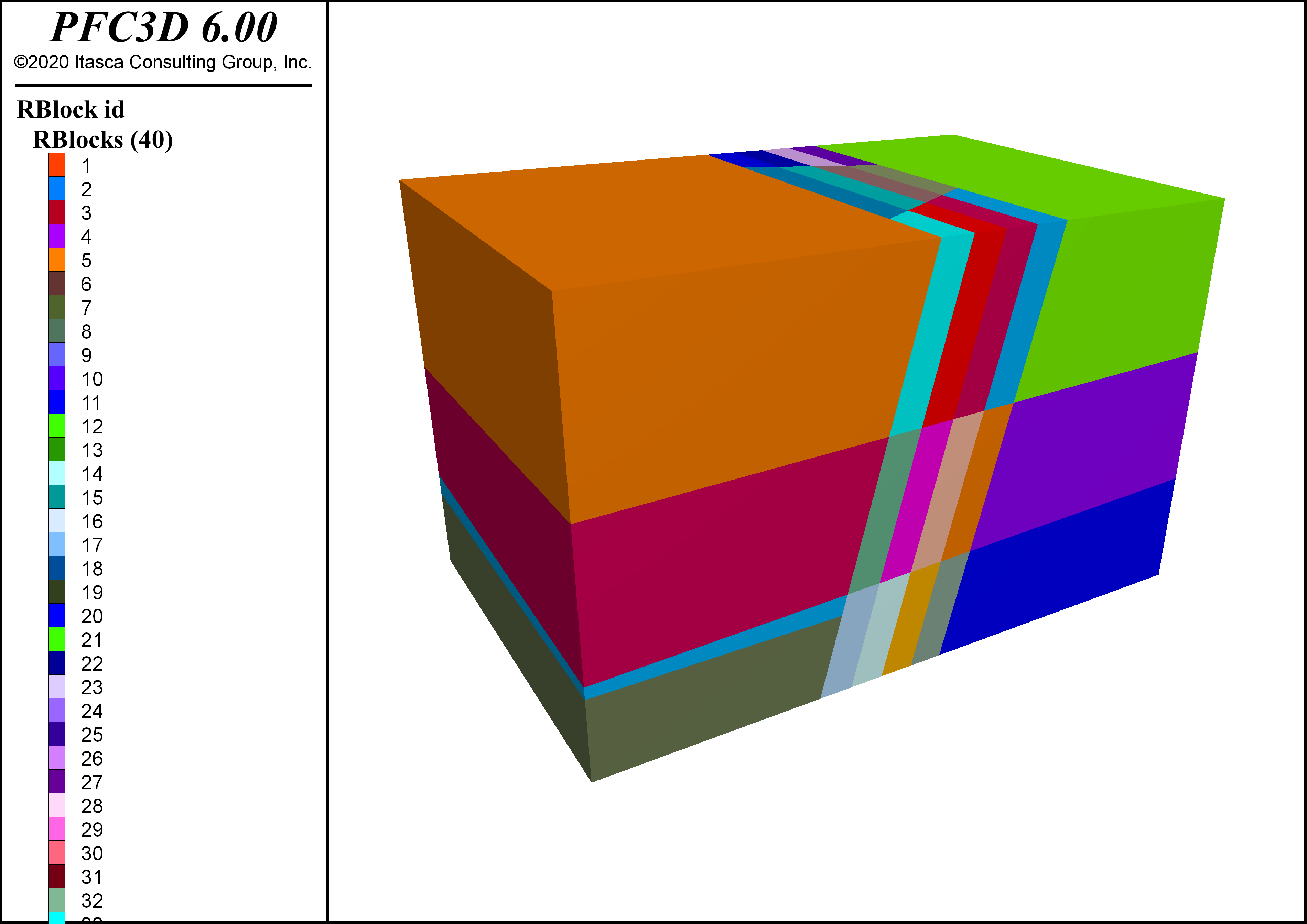
The same simple wedge example is run in 3DEC and the blocks are exported to PFC. By default, the PFC data file is called “rigidblock.p3dat”. This can be changed with the filename keyword. The resulting PFC model is shown in Figure 3. This example can be run in the PFC demonstration version.

Figure 3: PFC rigid blocks created from exporting a 3DEC model.
Exporting to UDEC
The block to-udec command can be used to export a section of a 3DEC model to UDEC. Specify a plane using the keywords origin, and either normal, or dip and dip-direction. A filename may also be specified (by default it is “sectionfrom3DEC.uddat”. The resulting file is a UDEC data file that can be called to create blocks in UDEC. Block groups from the 3DEC model will be preserved in the UDEC model.
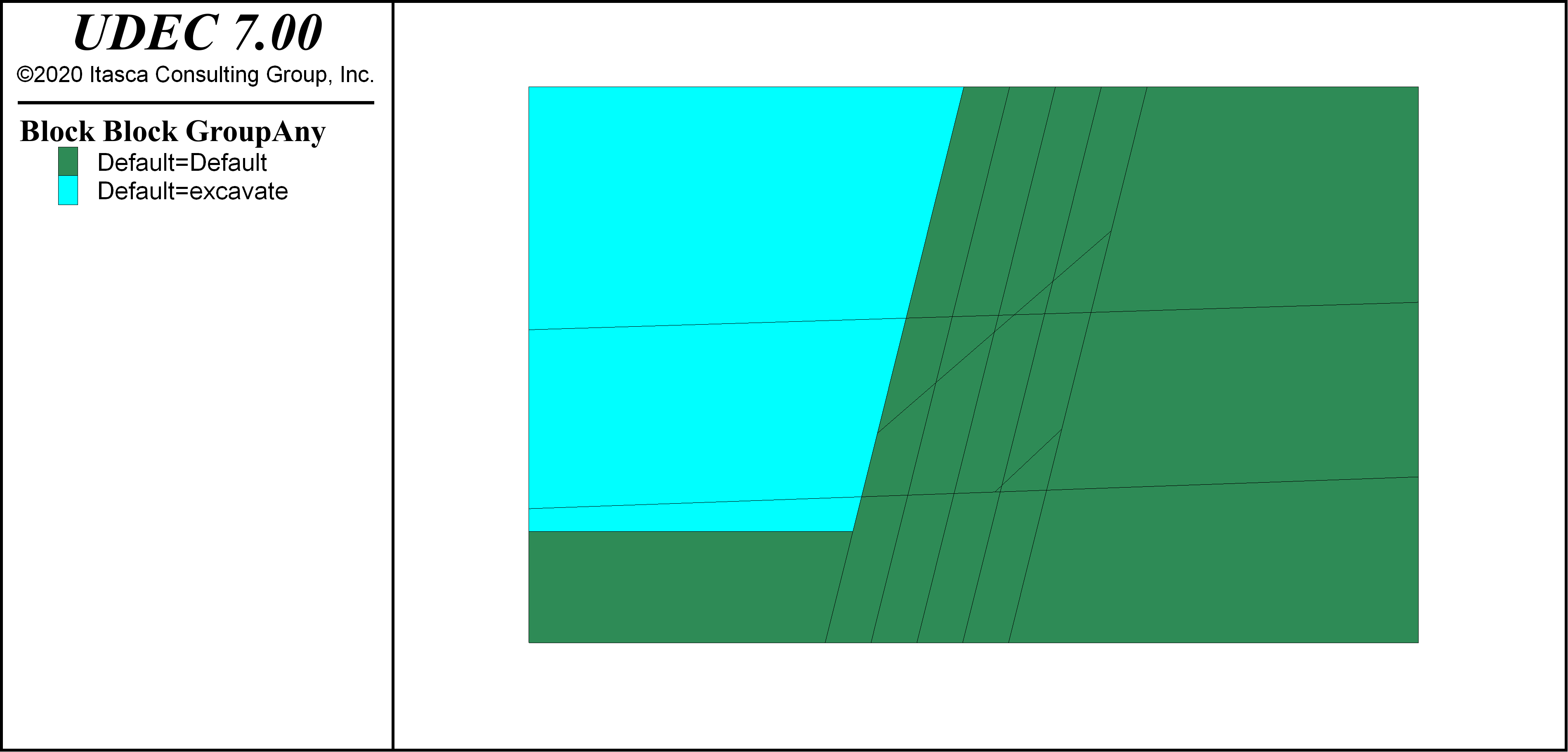
The resulting UDEC model from the simple wedge example is shown in Figure 4. This model can be run in the demonstration version of UDEC.

Figure 4: UDEC blocks created from exporting a 3DEC model.
| Was this helpful? ... | Itasca Software © 2024, Itasca | Updated: Nov 12, 2025 |
