Plastic Hinge Formation (with beam elements)
Problem Statement
Note
To view this project in FLAC3D, use the menu command . The main data files used are shown at the end of this example. The remaining data files can be found in the project.
This example demonstrates two methods, referred to as the single- and double-node methods, by which one can model the initiation and subsequent behavior of a plastic hinge in a beam.[1] The single-node method involves specifying the limiting plastic moment (via the plastic-moment property of the beam) that can be carried by the elements making up the beam. With this method, a hypothetical hinge can form between beam elements; however, because the elements are joined with a single node, a true discontinuity in the rotational motion cannot develop at these locations. The double-node method involves creating double nodes at each potential hinge location, and then appropriately linking these nodes together. The double nodes allow a discontinuity in the rotation to occur when the limiting plastic moment is reached. The double-node method should be applied to calculate the large-strain, post-failure behavior of a structure. If it is only necessary to determine the solution at the limiting plastic moment, then the single-node method is sufficient. In the following discussion, we first define the example problem, and then solve it in two ways by using the single-node method, and then using the double-node method.
Analytical Solution
A concentrated vertical load \((P)\) is applied at the center of a 10 m long, simply supported beam with a plastic-moment capacity, \(M^P\), of 25 kN-m. The system, along with the shear-force and bending-moment distributions, is shown in Figure 1. From these shear and moment diagrams, we find that the specified plastic-moment capacity corresponds with a maximum vertical load of 10 kN and a maximum shear force of 5 kN. If we apply a constant vertical velocity to the beam center, we expect that the limiting values of moment and shear force will be 25 kN-m and 5 kN, respectively.
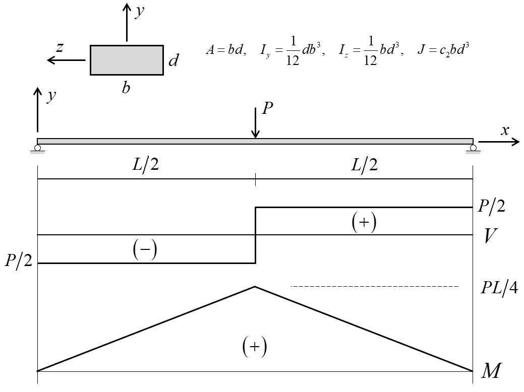
Figure 1: Simply supported beam with single concentrated load and shear-force and bending-moment distributions.
Particular Problem
The particular problem to be considered is defined as follows. The beam has a 10-m length (\(L = 10 \textrm{ m}\)), and a rectangular cross section with \(b = 1.0 \textrm{ m}\) and \(d = 100 \textrm{ mm}\). The cross-sectional properties (obtained via the expressions in Figure 1) are
where the constant \(c_2 = 0.312\) (Crandall et al., 1978, Table 6.1). The beam is comprised of structural steel, and is assumed to behave as an isotropic elastic material with
The properties \(\{ A, I_y, J, \nu \}\) are not relevant for this problem; however, they are needed as input for the FLAC3D model.
FLAC3D Models, Results and Discussion
Single-Node Method
The FLAC3D model demonstrating the single-node method (see “PlasticBeamHinge-Single.dat”) is created by issuing a single structure beam create command and specifying two segments. This produces a model containing 2 elements and 3 nodes, with both elements sharing the center node as shown in Figure 2. The beam is assigned the properties listed above and, in addition, the plastic-moment capacity is set to 25 kN-m. The beam element coordinate system is aligned with the global coordinate system by setting the direction-y property equal to \((0,1,0)\). Simple supports are specified at the beam ends by restricting translation in the \(y\)-direction. A constant vertical velocity is applied to the center node, and the moment and shear force acting at the right end of element 1 are monitored during the calculation to determine when the limiting values have been reached. Note that we specify combined local damping for this problem in order to eliminate the ringing that can occur with the default local damping scheme when the system is being driven by a constant motion.
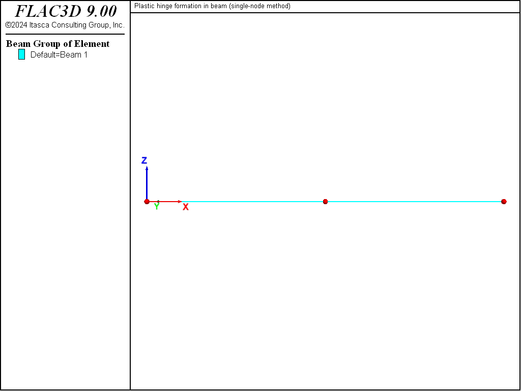
Figure 2: Geometry of the FLAC3D model showing mesh (2 elements and 3 nodes) and global coordinate system.
We find that the limiting values of moment and shear force are equal to the analytical values of 25 kN-m and 5 kN, respectively, as shown in Figures 3 and 4. The bending-moment and shear-force distributions correspond with the analytical solution as shown in Figures 5 and 6. A discontinuity in the rotational motion at the center location cannot develop, because there is only a single node at this location.
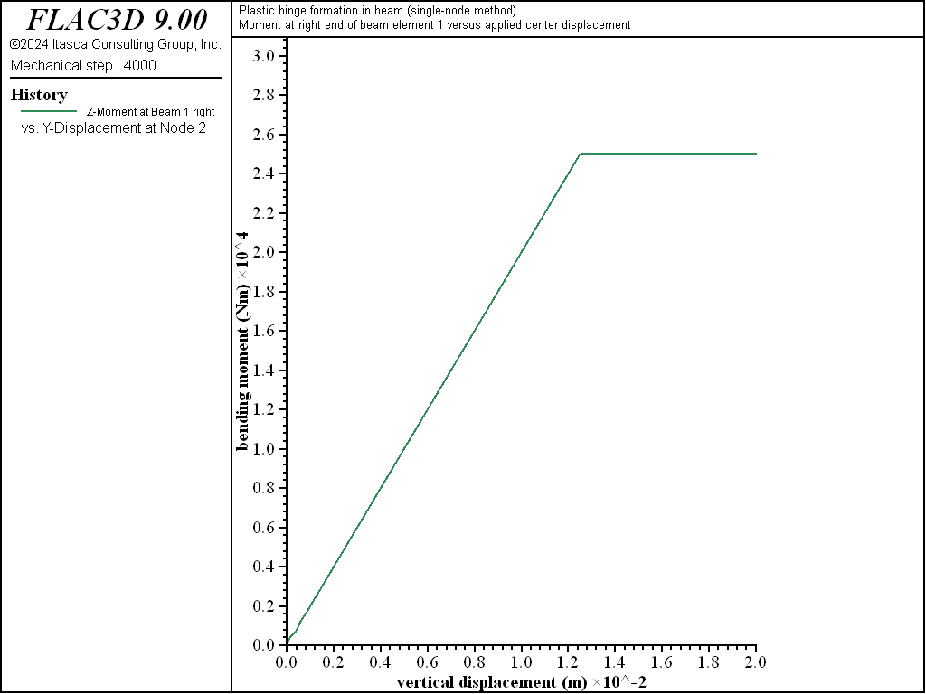
Figure 3: Moment at right end of element 1 versus applied center displacement (single-node method).
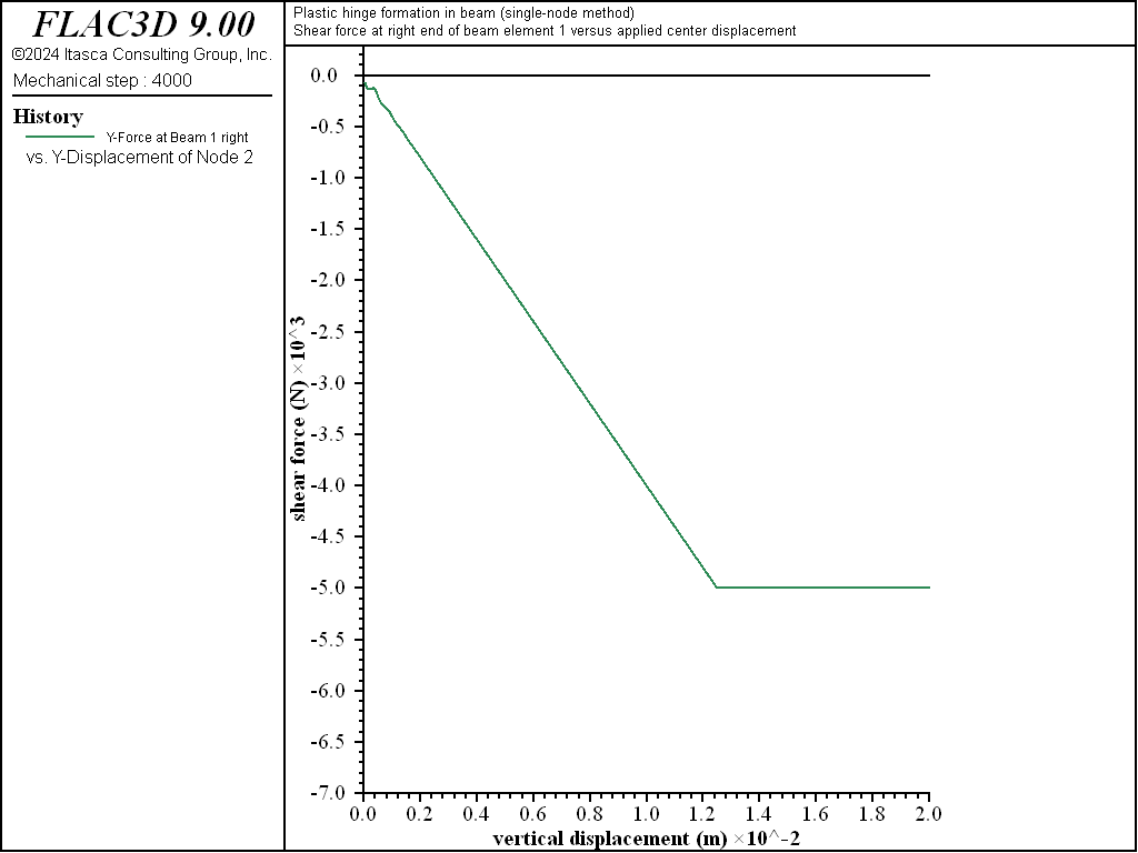
Figure 4: Shear force at right end of element 1 versus applied center displacement (single-node method).
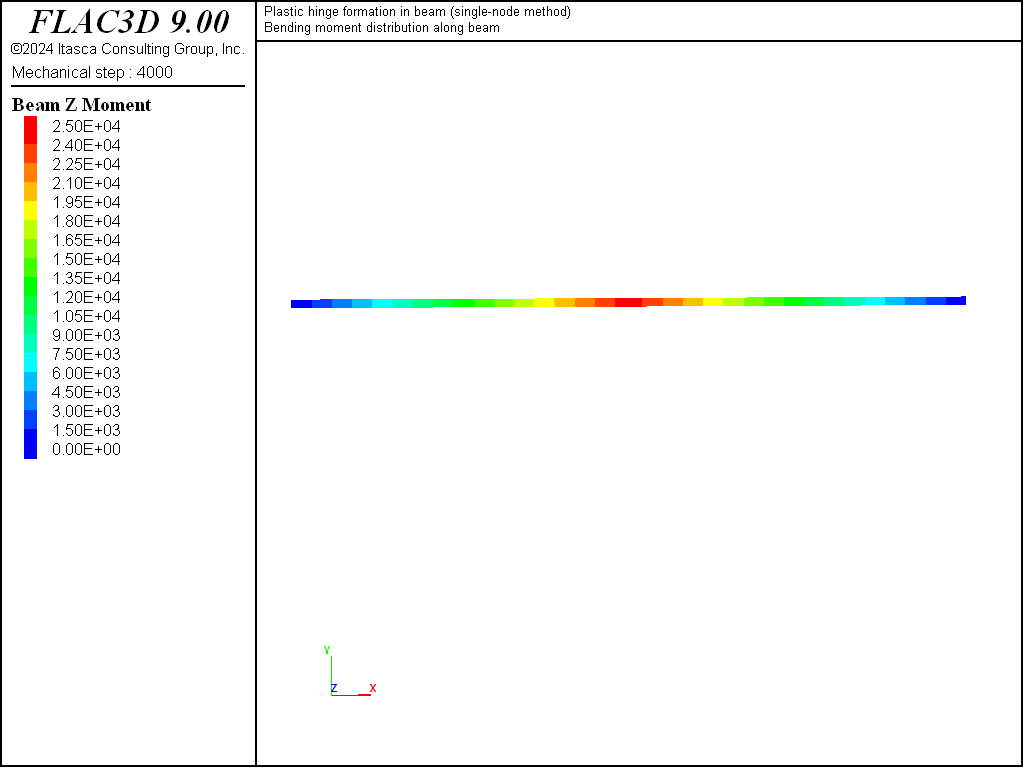
Figure 5: Bending-moment distribution at limit condition (single-node method).
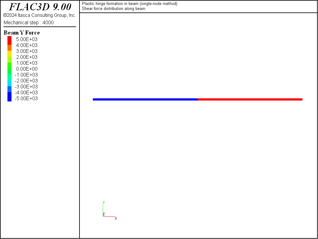
Figure 6: Shear-force distribution at limit condition (single-node method).
Double-Node Method
The FLAC3D model demonstrating the double-node method (see “PlasticHingeBeam-Double.dat”) is created by issuing two separate structure beam create commands. This produces a model containing two elements and four nodes. Going from left to right, the left element uses nodes 1 and 2, and the right element uses nodes 3 and 4. Note that nodes 2 and 3 lie in the same location, but they will not interact with one another. We now create an appropriate linkage between nodes 2 and 3 with the following commands[2]:
struct node join range component-id 2
struct link attach rotation-z normal-yield
struct link property rotation-z area 1.0 stiffness 6.4e8 ...
                     yield-compression 25e3 yield-tension 25e3
The first command creates a node-to-node link from node 2 to node 3, and the attachment conditions are rigid for all degrees-of-freedom. The second command inserts a normal-yield spring in the \(z\)-rotational direction of the link. The final command set the properties of this normal-yield spring as follows. We set all areas to unity, and we set both the compressive and tensile yield strengths equal to the desired plastic-moment capacity of 25 kN-m. Finally, we set the spring stiffness equal to a value that is large enough to make the spring deformation small relative to the beam deformation. We determine this value by summing the rotational stiffnesses of the two elements that use the spring (each rotational stiffness is \(4EI/L\), where \(L\) is element length) and multiplying this value by 10.
Now that the double nodes have been appropriately linked to one another, the beam is assigned the same properties as listed above; but we do not specify a plastic-moment capacity, because we want the moment at the center to be limited by the strength of the normal-yield spring. The beam element coordinate system is aligned with the global coordinate system by setting the direction-y property equal to \((0,1,0)\). Simple supports are specified at the beam ends by restricting translation in the \(y\)-direction. A constant vertical velocity is applied to the target node, and the moment and shear force acting at the right end of element 1 are monitored during the calculation to determine when the limiting valus have been reached. Note that we specify combined local damping for this problem in order to eliminate the ringing that can occur with the default local damping scheme when the system is being driven by a constant motion.
We find that the limiting values of moment and shear force are equal to the analytical values of 25 kN-m and 5 kN, respectively, as shown in Figures 7 and 8. The bending-moment and shear-force distributions correspond with the analytical solution as shown in Figures 9 and 10. A discontinuity in the rotational motion at the beam center has developed — the rotation of nodes 2 and 3 are nonzero and equal and opposite to each other (structure node list displacement).

Figure 7: Moment at right end of element 1 versus applied center displacement (double-node method).

Figure 8: Shear force at right end of element 1 versus applied center displacement (double-node method).
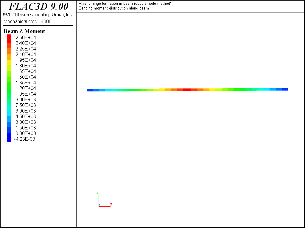
Figure 9: Bending-moment distribution at limit condition (double-node method).
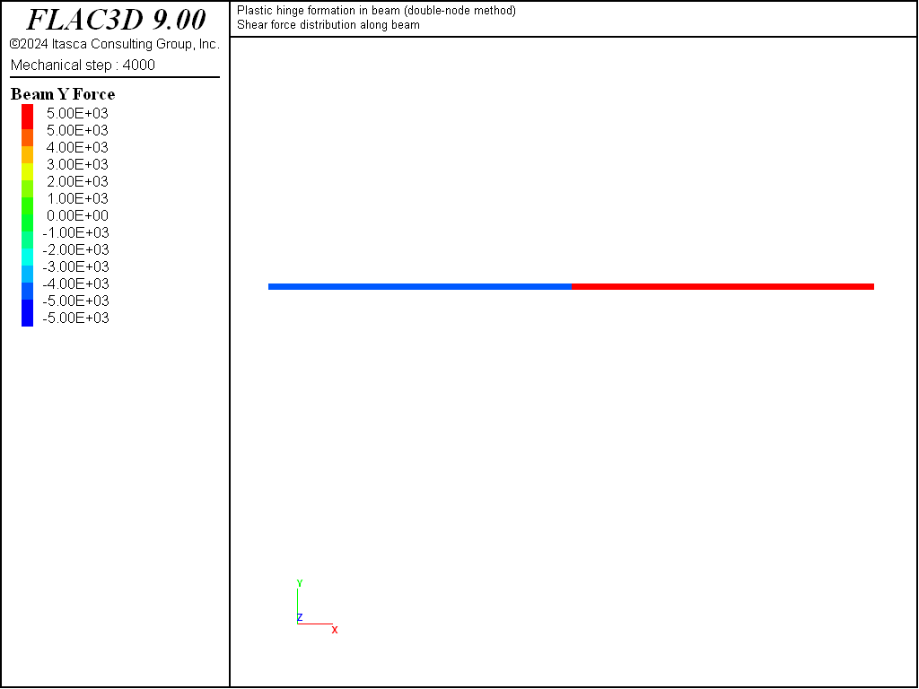
Figure 10: Shear-force distribution at limit condition (double-node method).
Double-Node Cantilever
The preceding two examples demonstrate that both the single-node and the double-node methods produce the same behavior near the limiting moment; however, if we were to continue loading the structure in a large-strain fashion, then the double-node method would produce more reasonable results because it allows a discontinuity to develop in the rotation at the center. We illustrate this behavior by modifying the double-node example to represent a cantilever beam (fixed at the left end) with a vertical load applied at the free end (see “PlasticHingeBeam-Cantilever.dat”). The problem is run in large-strain mode. The final structural configuration and moment distribution are shown in Figure 11. The double-node method allows a discontinuity to develop in the rotation at the beam center.
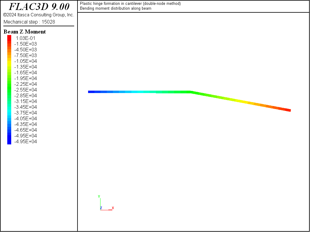
Figure 11: Final structural configuration and bending-moment distribution in cantilever (double-node method).
Reference
Crandall, S.H., N.C. Dahl and T.J. Lardner. An Introduction to the Mechanics of Solids, Second Edition, New York: McGraw-Hill Book Company (1978).
Endnotes
Data Files
PlasticHingeBeam-Single.dat
model new
model title 'Plastic hinge formation in beam (single-node method)'

; Create beam and assign properties.
structure beam create by-line (0,0,0) (10,0,0) segments 2

; Assign beam properties
structure beam cmodel assign elastic
structure beam property young 200e9 poisson 0.30
structure beam property cross-sectional-area 0.1 ...
                     moi-y 8.33e-3 moi-z 8.33e-5 torsion-constant 3.12e-4 ...
                     direction-y (0,1,0)
structure beam property plastic-moment 25e3

; Assign boundary conditions.
structure node fix velocity-y range position-x 0.0 position-x 10.0 union
                           ; simple support at left and right end
structure node fix velocity-y range position-x 5.0
                           ; Apply constant vertical velocity
structure node initialize velocity-y -5e-6 local range position-x 5.0
                           ; to center node.

; Take histories to monitor response.
structure node history name='disp' displacement-y position (5,0,0)
                           ; y-displacement of center node
structure beam history name='mom' moment-z end 2 position (2.5,0,0)
                           ; moment
structure beam history name='force' force-y end 2 position (2.5,0,0)
                           ; shear force

structure mechanical damping combined-local
model large-strain off
model cycle 4000 ; 20 mm total displacmeent
model save 'SingleNode'
PlasticHingeBeam-Double.dat
model new
model title 'Plastic hinge formation in beam (double-node method)'

; Create two separate beams that do not share center node.
structure beam create by-line (0,0,0) ( 5,0,0) id 1 segments 1
structure beam create by-line (5,0,0) (10,0,0) id 2 segments 1

; Create a link at the overlapping nodes and set link properties.
structure node join range component-id 2
structure link attach rotation-z normal-yield
structure link property rotation-z area 1.0 stiffness 6.4e8 ...
                     yield-compression 25e3 yield-tension 25e3

; Assign beam properties
structure beam cmodel assign elastic
structure beam property young 200e9 poisson 0.30
structure beam property cross-sectional-area 0.1 ...
                     moi-y 8.33e-3 moi-z 8.33e-5 torsion-constant 3.12e-4 ...
                     direction-y (0,1,0)

; Assign boundary conditions.
structure node fix velocity-y range position-x 0.0 position-x 10.0 union
                     ; simple support at left and right end
; Apply constant vertical velocity to center node-3 ---
; must apply velocity to target node.
structure node fix velocity-y range position-x 5.0
                     ; Apply constant vertical velocity
structure node initialize velocity-y -5e-6 local range component-id 3
                     ; to the target node.

; Take histories to monitor response.
structure node history name='disp' displacement-y position (5.0,0,0)
                     ; y-displacement of center node
structure beam history name='mom' moment-z end 2 position (2.5,0,0)
                     ; moment
structure beam history name='force' force-y end 2 position (2.5,0,0)
                     ; shear force

structure mechanical damping combined-local
model large-strain off
model cycle 4000 ; 20 mm total displacmeent
model save 'DoubleNode'
PlasticHingeBeam-Cantilever.dat
model new
model title 'Plastic hinge formation in cantilever (double-node method)'

; Create two beams
structure beam create by-line (0,0,0) (5,0,0)  id 1 segments 1
structure beam create by-line (5,0,0) (10,0,0) id 2 segments 1

; Join nodes, and make the z rot link plastic
structure node join range component-id 2
structure link attach rotation-z normal-yield
structure link property rotation-z area 1.0 stiffness 6.4e8 ...
                     yield-compression 25e3 yield-tension 25e3

; Assign beam properties
structure beam cmodel assign elastic
structure beam property young 200e9 poisson 0.30
structure beam property cross-sectional-area 0.1 ...
                     moi-y 8.33e-3 moi-z 8.33e-5 torsion-constant 3.12e-4 ...
                     direction-y (0,1,0)

; Assign boundary conditions
structure node fix velocity rotation range position-x 0 ; fully fix left end
structure node apply force=(0,-5.0e3,0) range position-x 10.0 ; apply force at tip

structure mechanical damping combined-local
model large-strain on
model solve convergence 1.0
model save 'Cantilever'
| Was this helpful? ... | Itasca Software © 2024, Itasca | Updated: Nov 12, 2025 |
