Elastic-Plastic Beam with Two Plastic Hinges
Problem Statement
Note
There are two projects, each in its own subdirectory. To view them in FLAC3D, use the menu command . Choose “Structure/Beam/TwoHinges” and select the desired project. The main data files used are shown at the end of this example. The remaining data files can be found in the project.
The collapse loads for beams of rectangular and circular cross section subjected to a slowly increasing midpoint deflection are computed and compared with analytical solutions for a beam with its left end simply supported and right end fixed. This problem quantifies the ability of the Euler-Bernoulli beam element with the von Mises constitutive law to capture the progressive and localized yielding that occurs at the plastic-hinge locations at the midpoint and fixed end, and that culminates in the collapse of the beam. The collapse load is also computed using a beam with an isotropic elastic constitutive model and a specified plastic moment capacity (enforced at the beam nodes).[1]
Introduction
Beams of ductile material (structural steel or aluminum) do not ordinarily fracture under static loading but fail through excessive deflection. For such beams, if they are of relatively thick section to preclude local buckling, the maximum bending moment is that which corresponds to plastic yielding throughout the section. This maximum moment, or plastic moment, is usually denoted by \(M_p\) and can be calculated by the formula \(M_p = \sigma_Y Z\), where \(\sigma_Y\) is the lower yield point of the material and \(Z\), called the plastic section modulus, is the arithmetical sum of the statical moments about the neutral axis of the parts of the cross section above and below that axis. The deformation associated with the plastic moment is localized at the section and forms a plastic hinge. The plastic moment is always greater than the moment required to just stress the extreme fiber to the lower yield point. This moment, or yield moment, is usually denoted by \(M_y\) and can be calculated by the formula \(M_y = M_p / S\) where \(S\) is the shape factor that depends on the form of the cross section. Plastic section moduli and shape factors for various cross sections are given in Table A.1 of Budynas and Sadegh (2020). A beam of ductile material will not collapse until the plastic moment has been developed at each of several critical sections to produce a kinematic mechanism. The accuracy of this approach to determine collapse load has been proved by good agreement between computed and experimental collapse loads for both beams and frames (Budynas and Sadegh [2020]).
The creation of a plastic hinge in a rectangular beam of elastic-perfectly plastic material is described by Crandall et al. (1978) and sketched in image (a) of Figure 1. The maximum bending moment is at the beam center. At first the behavior is elastic, and the force \(P\) increases in linear proportion to the central deflection. In image (b) the point has been reached where the central bending moment is \(M_y\), and yielding begins at the top and bottom of the cross section. As the beam is deflected further, two zones of yielded material begin to grow, as shown in image (c). These zones extend from the center where the bending moment is greater than \(M_y\) out to the points where the bending moment is just equal to \(M_y\). The force \(P\) continues to grow during this stage of the deflection but at a less rapid rate than when the beam was entirely elastic. The yielded zones continue to grow as the screw jack is advanced until the configuration of image (d) is reached. At this point the yielded zones just touch at the center of the beam. The bending moment there is \(M_p\). Although the curvature at the central point is now infinite, the slope is still finite and continuous and so is the deflection. Since the central cross section is now completely plastic, any further motion of the screw jack can be accommodated by plastic flow at the center without any additional deformation of the rest of the beam and without further increase in the force \(P\). Thus further deflection of the beam results in a finite discontinuity in slope at the center as shown in image (e), and the beam collapses. This localized deformation is called a plastic hinge.
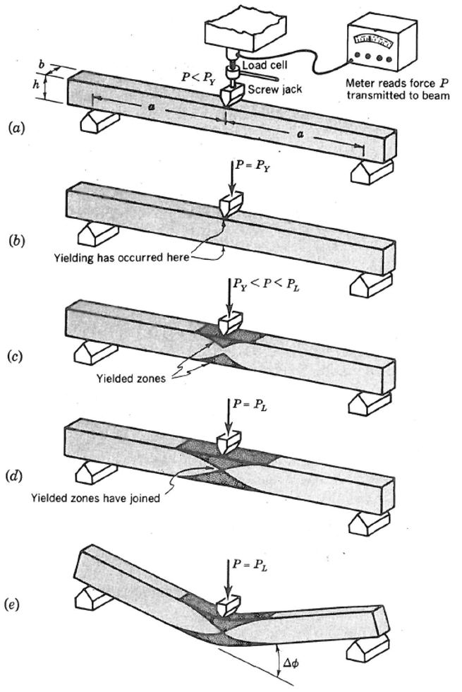
Figure 1: Creation of a plastic hinge as the center of the beam is forced downward by a screw jack. (From Fig. 7.30 of Crandall et al. [1978])
Analytical Solution
We consider a beam in which two plastic hinges form before collapse, and demonstrate how the numerical model matches: (1) the lateral deflection, shear-force and bending-moment distributions before any yielding has occurred; (2) the evolving response sketched in Figure 1 at each hinge location; and (3) the analytical collapse load.
A beam with its left end simply supported and right end fixed is subjected to a slowly increasing midpoint deflection \((\Delta)\) and associated load \((P)\) as shown in Figure 2. As the deflection is increased, a plastic hinge forms at point \(\bf C\) when the moment becomes equal to the plastic moment. As the deflection continues to increase, the moment at point \(\bf C\) remains equal to \(M_p\) until another plastic hinge forms at point \(\bf B\). These two plastic hinges create a kinematic mechanism, and the beam collapses.
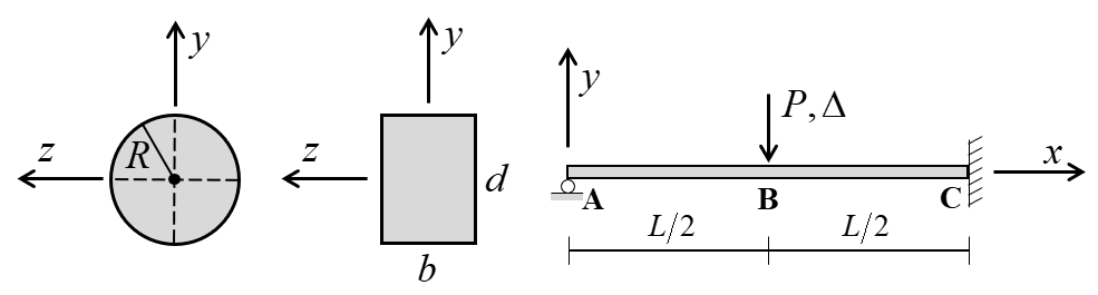
Figure 2: Beam of circular and rectangular cross section with point load and coordinate system used to express the analytical solution.
The lateral deflection, shear-force and bending-moment distributions for the elastic solution of simple beam theory (Euler-Bernoulli beam theory suitable for long thin beams) is given by AISC (1980, p. 2-118, case 13). The lateral deflection is
where \(P\) is applied load; \(E\) is Young’s modulus; \(I_z\) is moment of inertia with respect to \(z\) axis; \(L\) is beam length; \(b\) and \(d\) are width and depth, respectively, of the rectangular cross section, and \(R\) is radius of the circular cross section.
The shear-force and bending-moment distributions are
The bending moments at points \(\bf B\) and \(\bf C\) are
The yield and plastic moments of the cross sections are given by Budynas and Sadegh (2020, Table A.1):
where \(\sigma_Y\) is yield strength.
Yielding will begin at point \(\bf C\) when the moment magnitude equals the yield moment of the cross section:
where \(L\) is beam length. The load \((P_{yC})\) at which yielding begins at point \(\bf C\) is found by solving this expression for \(P\):
The collapse load \((P_c)\) is given by Budynas and Sadegh (2020, Table 8.13-1c):
Particular Problems
The particular problems to be considered are defined as follows. The geometry is defined by the properties:
The material is structural steel modeled as a von Mises material with no hardening:
where \(E\) is Young’s modulus; \(\nu\) is Poisson’s ratio; \(\sigma_Y\) is yield strength; and \(H\) is kinematic plastic (hardening) modulus.
For these geometric and material properties, yielding begins at point \(\bf C\) at loads of
and the collapse loads are
FLAC3D Model
The beams are modeled using a mesh of 16 Euler-Bernoulli beam elements as shown in Figure 3. The beam element coordinate system is aligned with the global coordinate system by setting the direction-y property equal to \((0,1,0)\). The moment capacity is not specified, and thus, it is infinite. The von Mises material model is used with the integration-point layouts shown in Figure 4. There are two integration points along the element length for both cross-sectional shapes; there are 2 and 12 integration points, respectively, across the beam width and through the beam depth for the rectangular cross section; and there are 2 and 7 integration points, respectively, in the radial and circumferential directions for the circular cross section. The simply-supported boundary condition (translational velocity fixed in the \(y\) direction) is assigned to the node at the left end. The fully-fixed boundary condition (translational velocity fixed in the \(x\) and \(y\) directions, and rotational velocity fixed along the \(z\) axis) is assigned to the node at the right end.
The center node is moved downwards at a velocity slow enough to maintain quasi-static conditions \((8 \times 10^{-8} \textrm{m/step})\) while measuring the applied load (as the unbalanced force acting in the \(y\) direction on the center node). Both of these quantities \((\Delta \textrm{ and } P)\) as well as the bending moments at points \(\bf B\) and \(\bf C\) are monitored as histories. The loads at which yielding begins at points \(\bf B\) and \(\bf C\) \((P_{yB} \textrm{ and } P_{yC})\) are found by checking when the outermost integration points at the left side of the element just to the right of center and the right side of the element at the right end have begun to yield. Combined damping is used with the default damping factor (see Combined Damping). The model is run in small-strain mode to correspond with the small-strain assumption of the analytical solution.
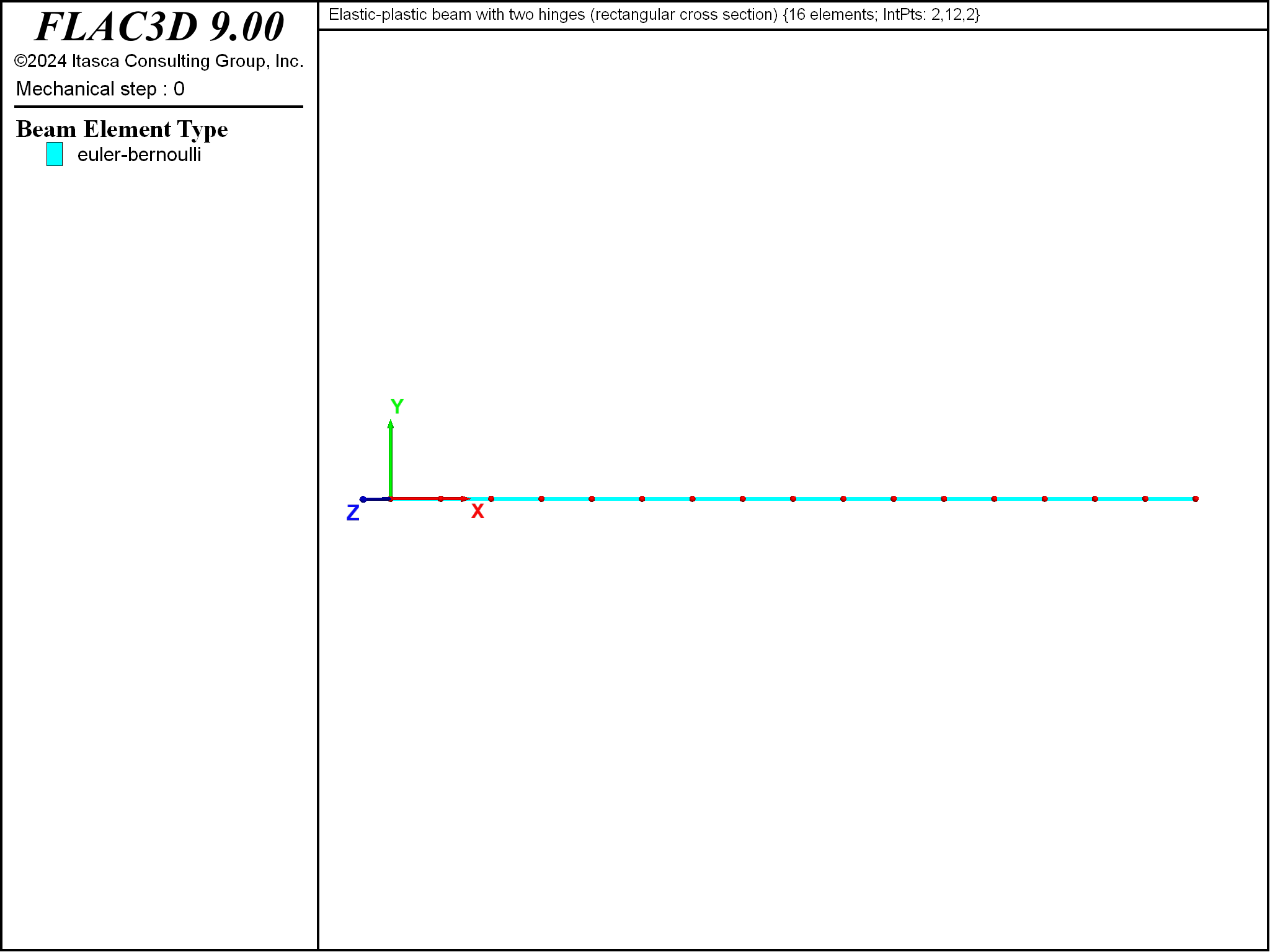
Figure 3: Geometry of the FLAC3D model showing mesh and global coordinate system.
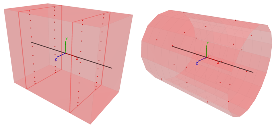
Figure 4: Integration points in a beam element with rectangular (left) and circular (right) cross section.
Results for Plastic Beam (rectangular cross section)
When the center deflection is 1.0 mm, the applied load is 8343 N, and there has been no yielding in the beam of rectangular cross section. The lateral deflection, shear-force and bending-moment distributions at this load stage are compared with the analytical elastic solutions in Figures 5 to 7. The computed lateral deflection, shear force and bending moment are within 0.2%, 0.0001% and 1.0%, respectively, of the analytical values at all sampling locations.
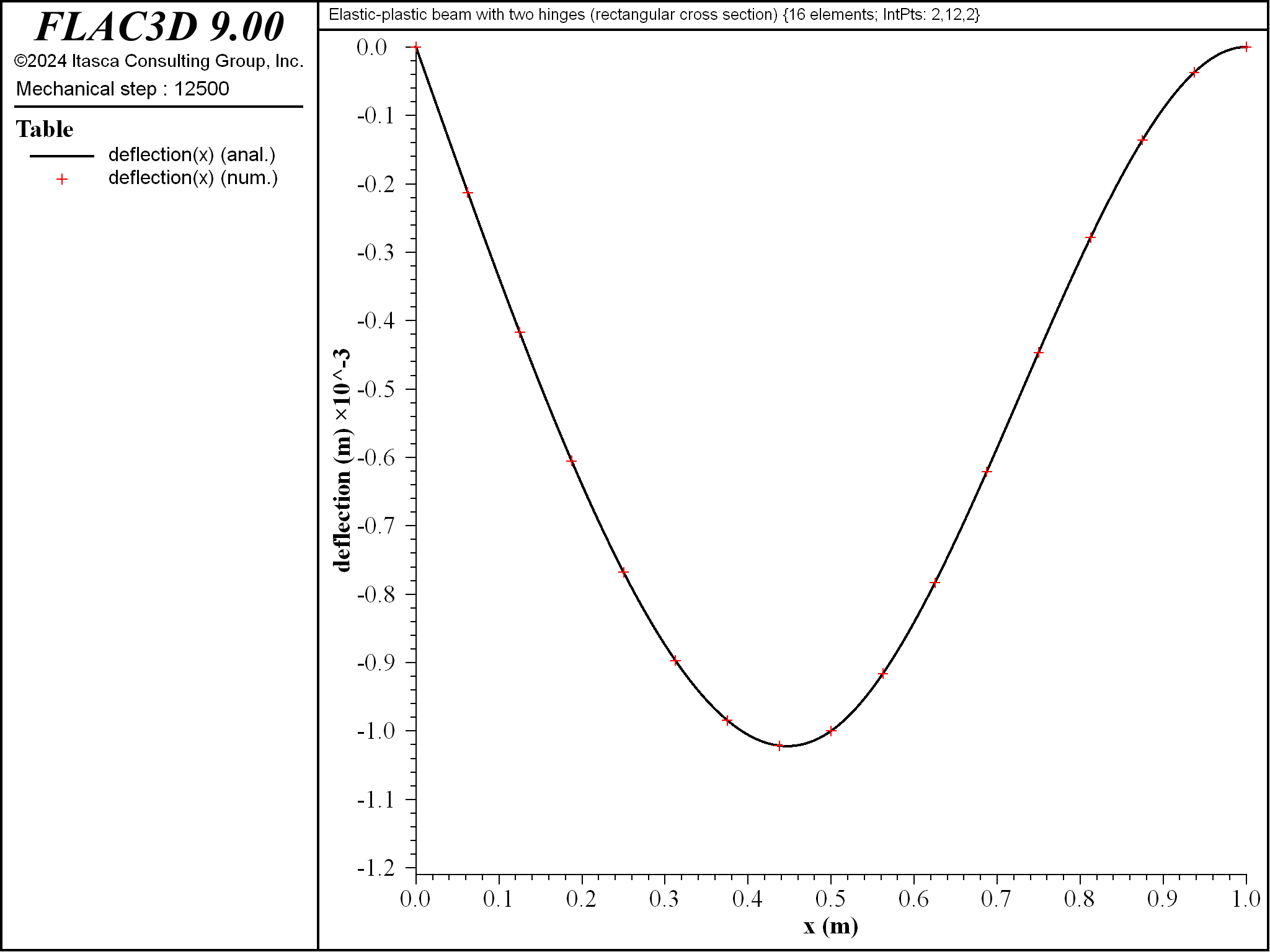
Figure 5: Lateral deflection for beam of rectangular cross section \((\Delta = 1 \textrm{ mm}\), \(P = 8343 \textrm{ N})\).
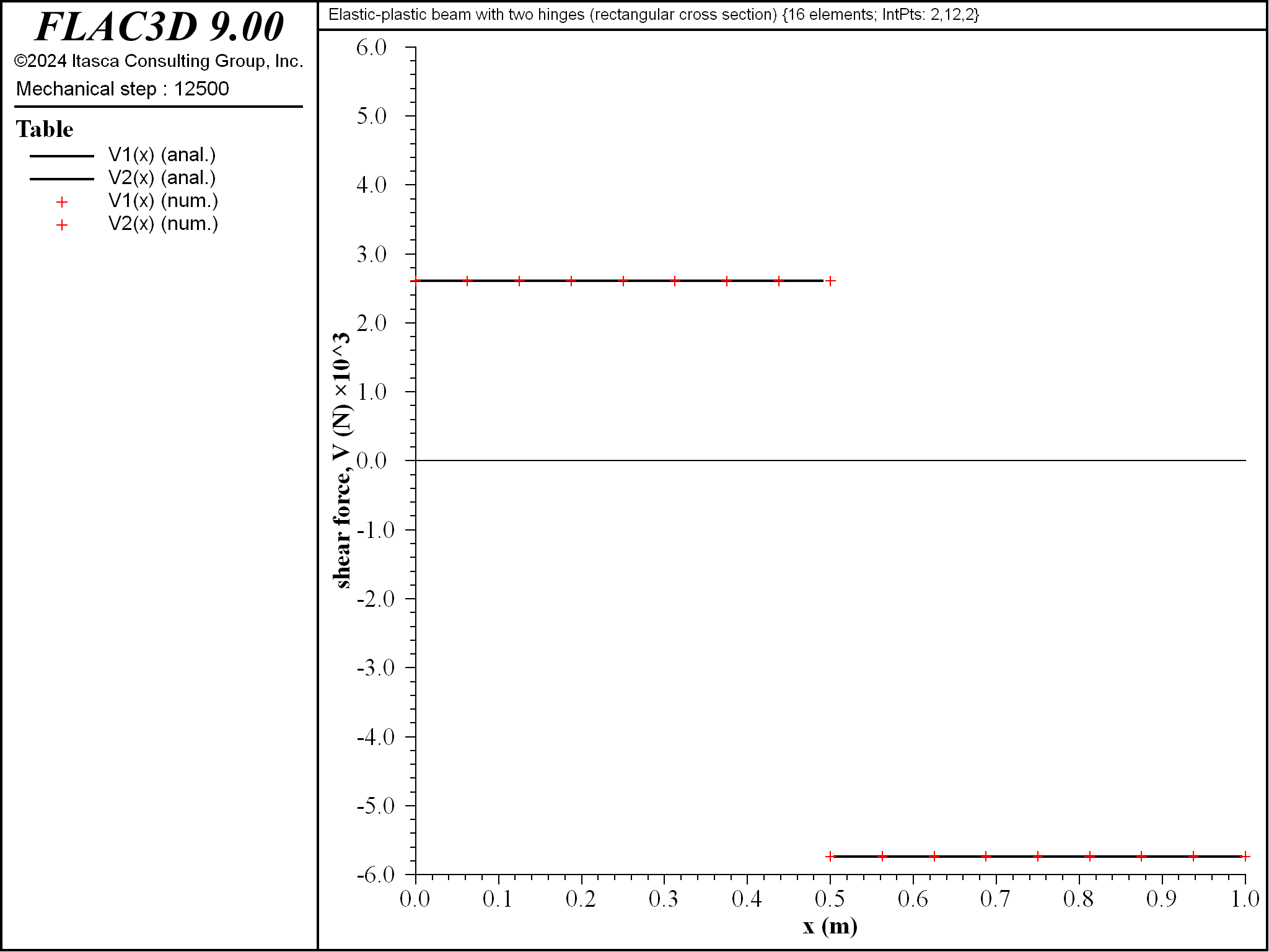
Figure 6: Shear-force distribution for beam of rectangular cross section \((\Delta = 1 \textrm{ mm}\), \(P = 8343 \textrm{ N})\).
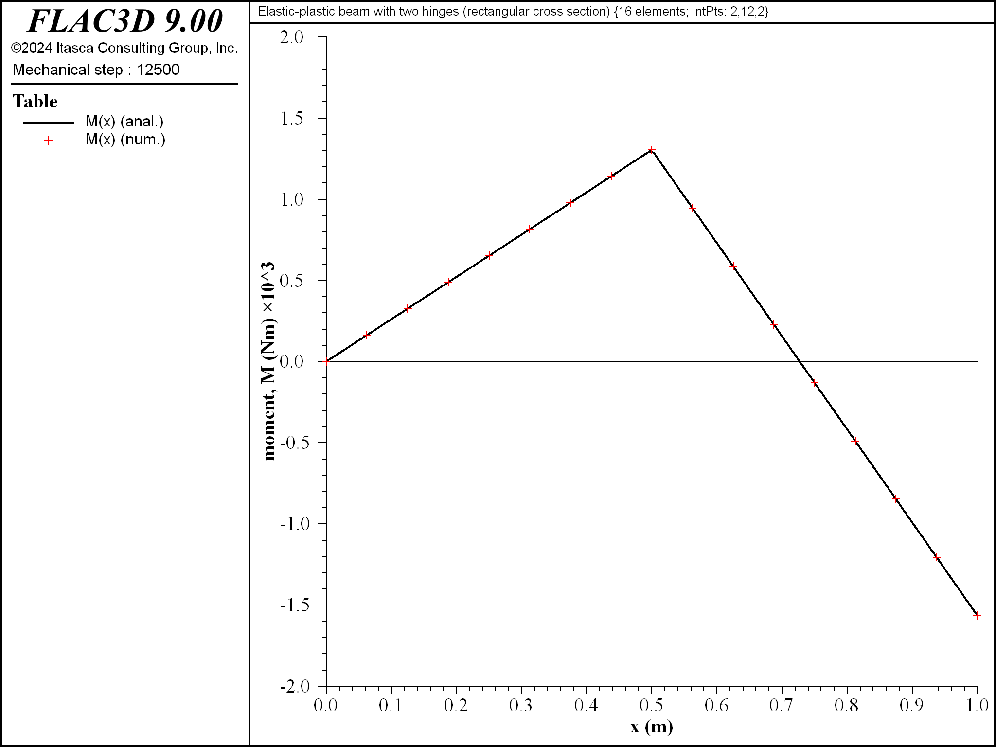
Figure 7: Bending-moment distribution for beam of rectangular cross section \((\Delta = 1 \textrm{ mm}\), \(P = 8343 \textrm{ N})\).
The response for the beam of rectangular cross section matches the response of the analytical model (see Figure 8).[2] The collapse load of 35653 N is within 4.2 percent of the analytical value. Hinges have formed at the center and right end. The center hinge has formed because all integration points on the plane of integration points on the right side of the element just to the left of center have yielded. The right-end hinge has formed because all integration points on the plane of integration points on the right side of the rightmost element have yielded.
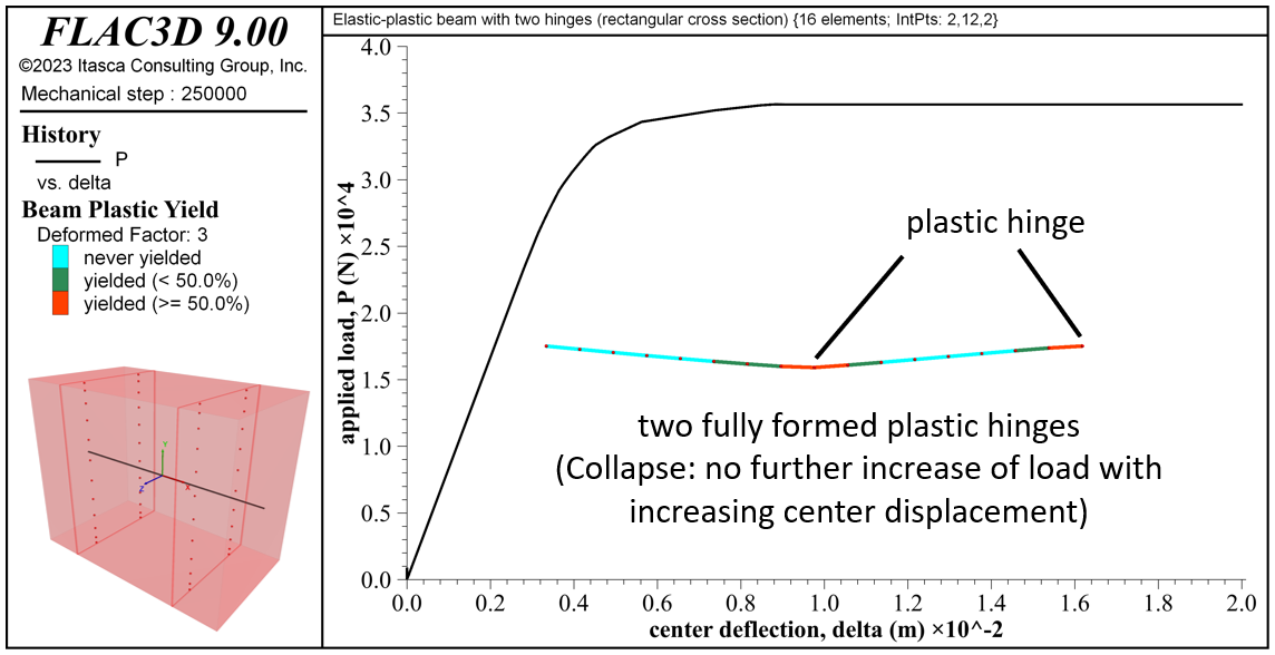
Figure 8: Load-displacement curve, final yield state, deformed shape (deformation factor: 3) and integration-point layout for the beam of rectangular cross section.
The material near point \(\bf C\) begins to yield before the material near point \(\bf B\) \((P_{yC} = 21711 \textrm{ N}\) and \(P_{yB} = 26189 \textrm{ N})\) (see Figure 9). The yielded regions expand and progress through the beam thickness to form plastic hinges at these locations when the collapse load is reached (see Figures 10 to 16).
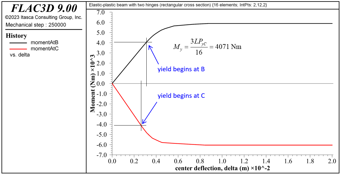
Figure 9: Bending-moments at points B and C versus center deflection for beam of rectangular cross section.
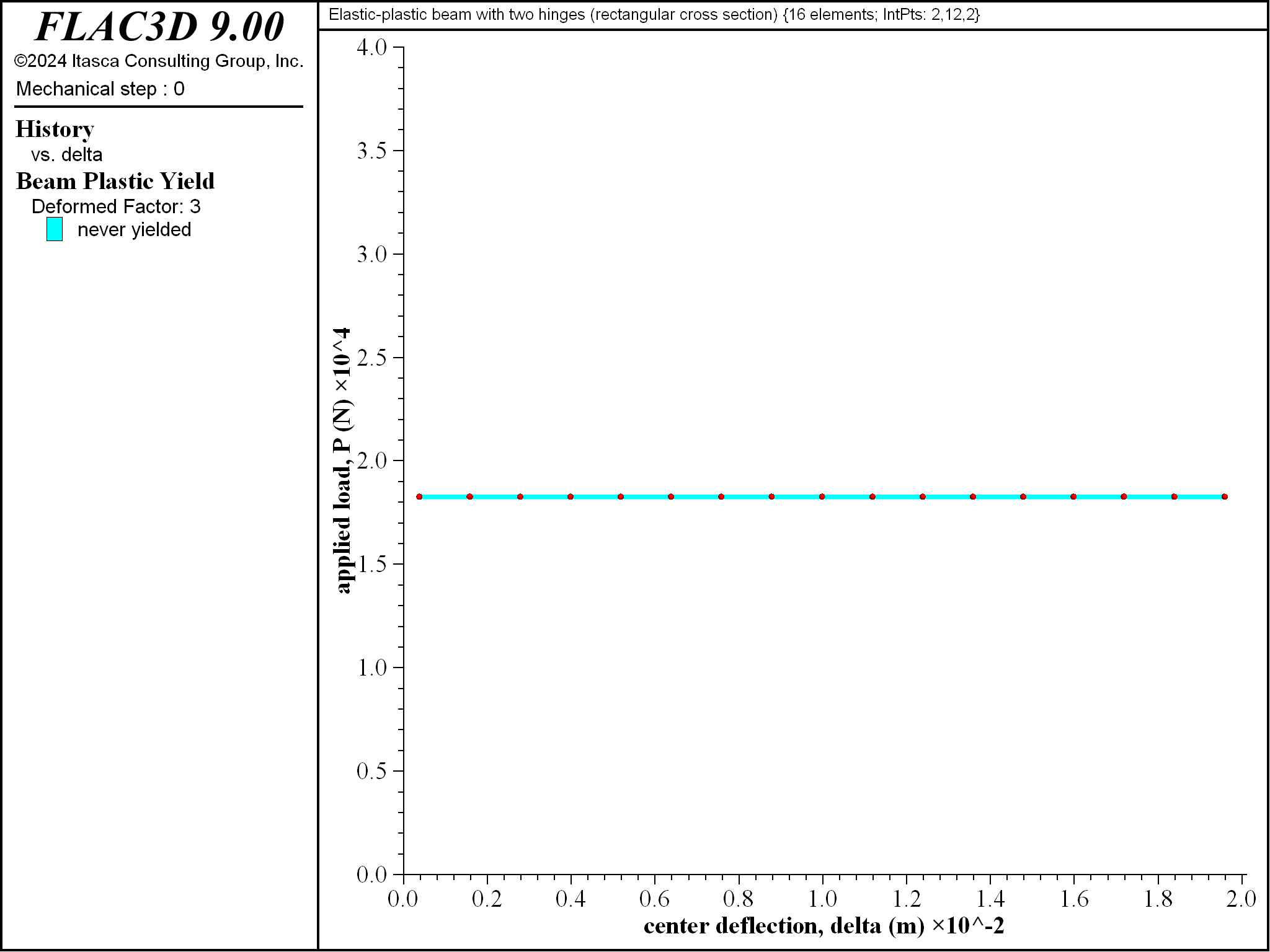
Figure 10: Progressive yielding for beam of rectangular cross section \((\Delta = 0)\)
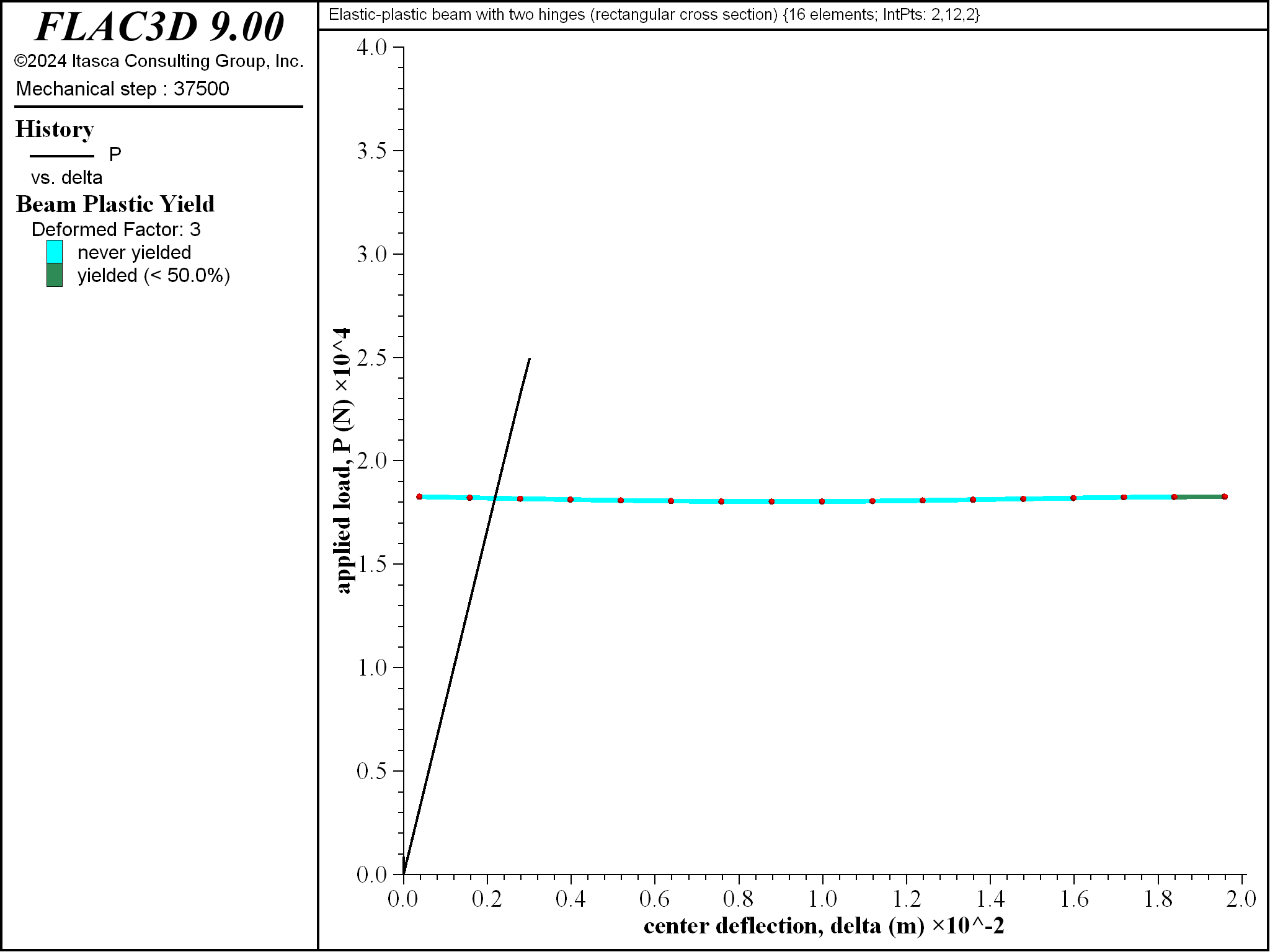
Figure 11: Progressive yielding for beam of rectangular cross section \((\Delta = 3 \textrm{ mm}\))`

Figure 12: Progressive yielding for beam of rectangular cross section \((\Delta = 3.5 \textrm{ mm}\))`
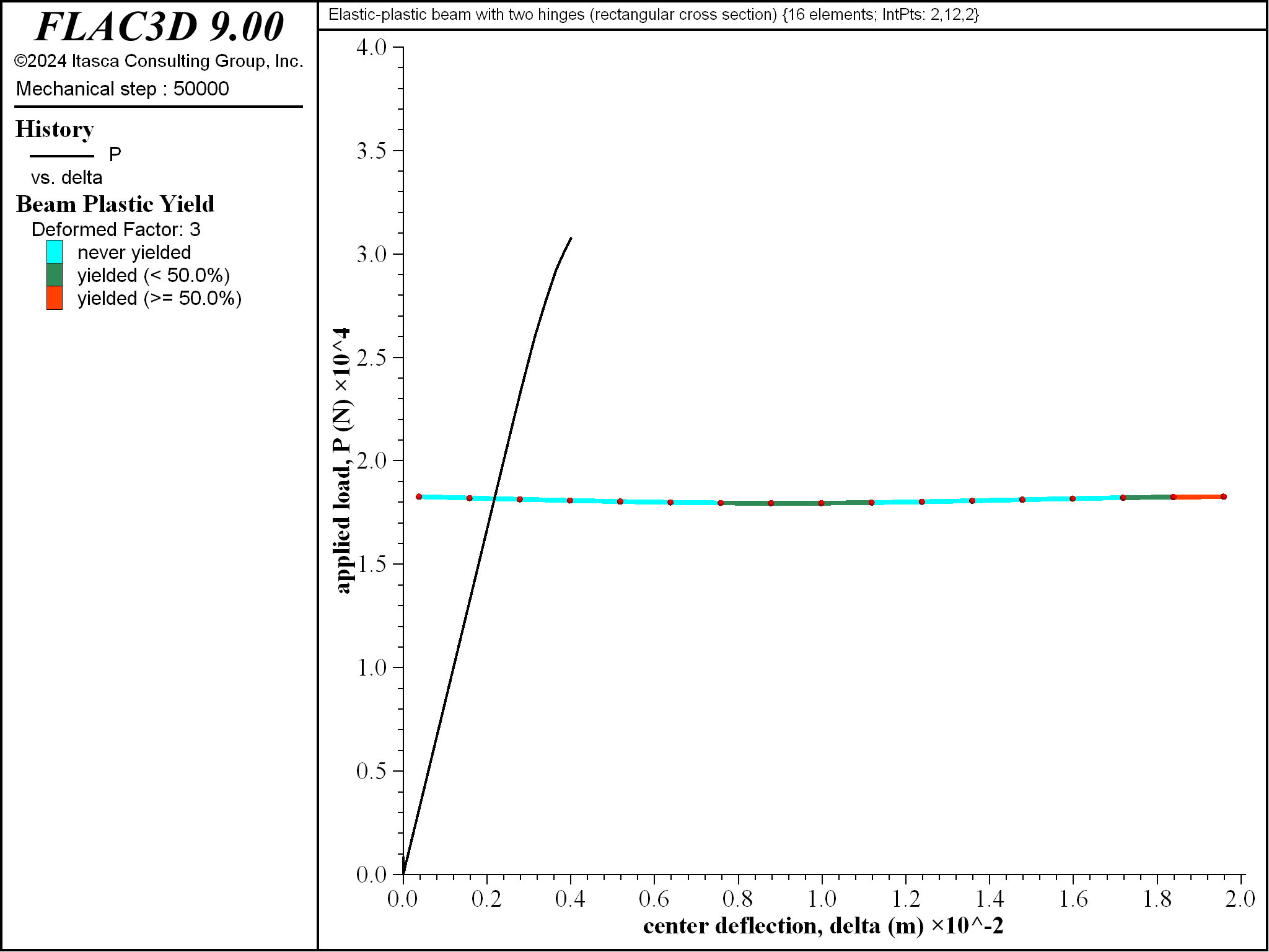
Figure 13: Progressive yielding for beam of rectangular cross section \((\Delta = 4 \textrm{ mm}\))`
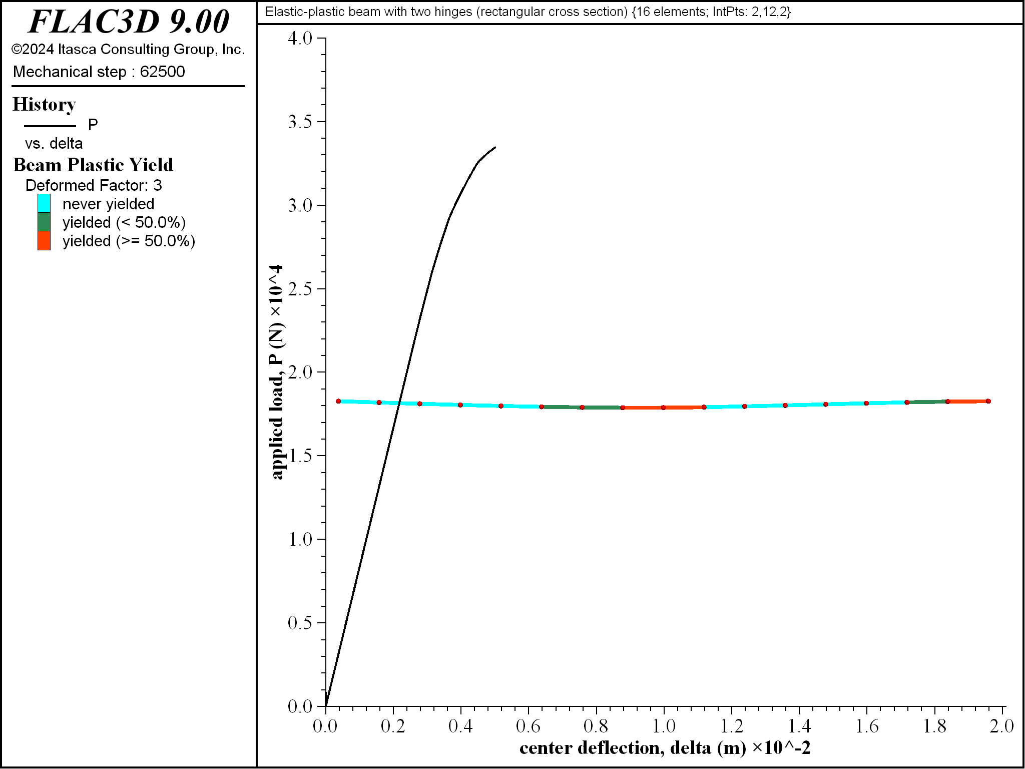
Figure 14: Progressive yielding for beam of rectangular cross section \((\Delta = 5 \textrm{ mm}\))`
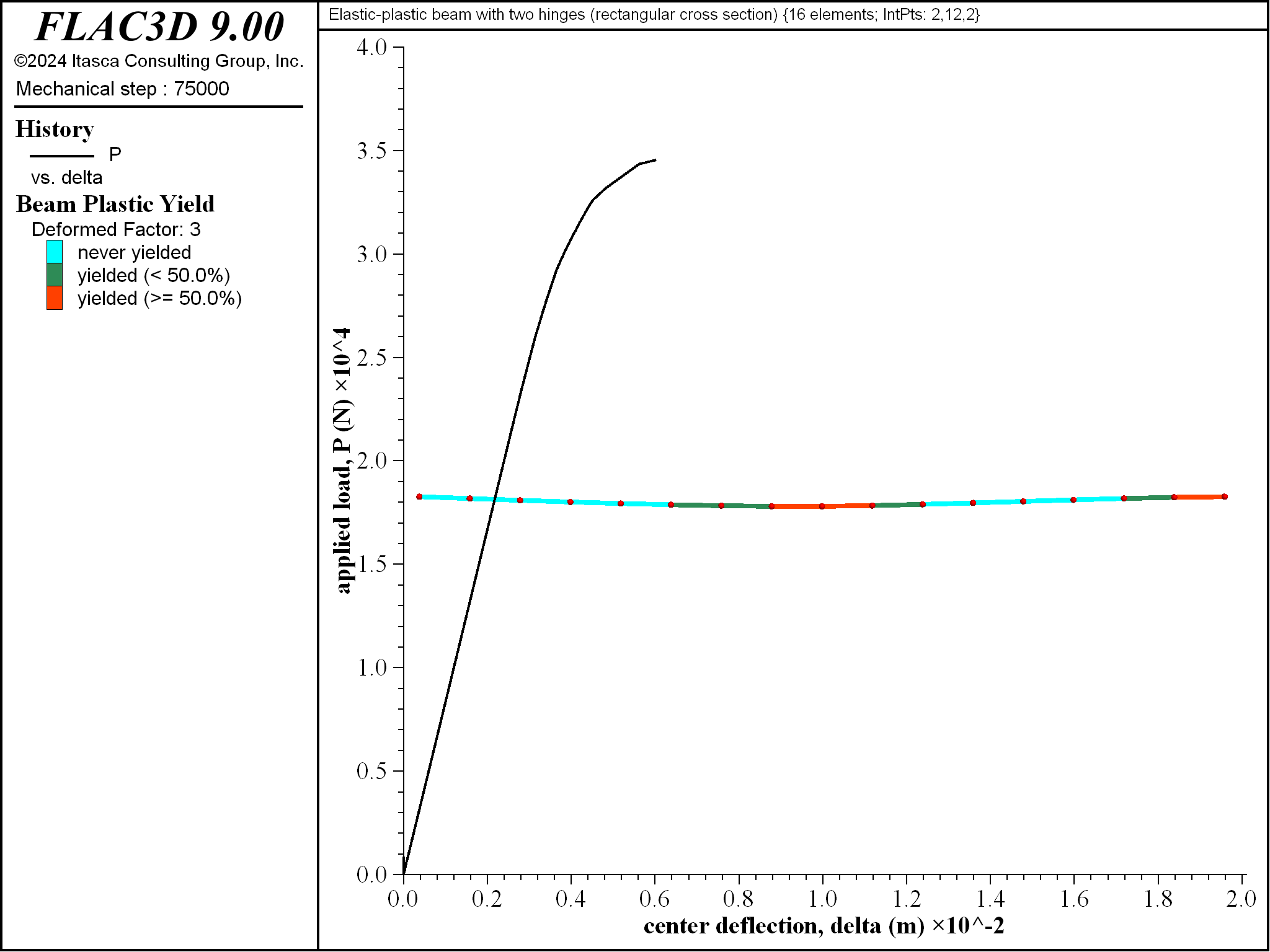
Figure 15: Progressive yielding for beam of rectangular cross section \((\Delta = 6 \textrm{ mm}\))`
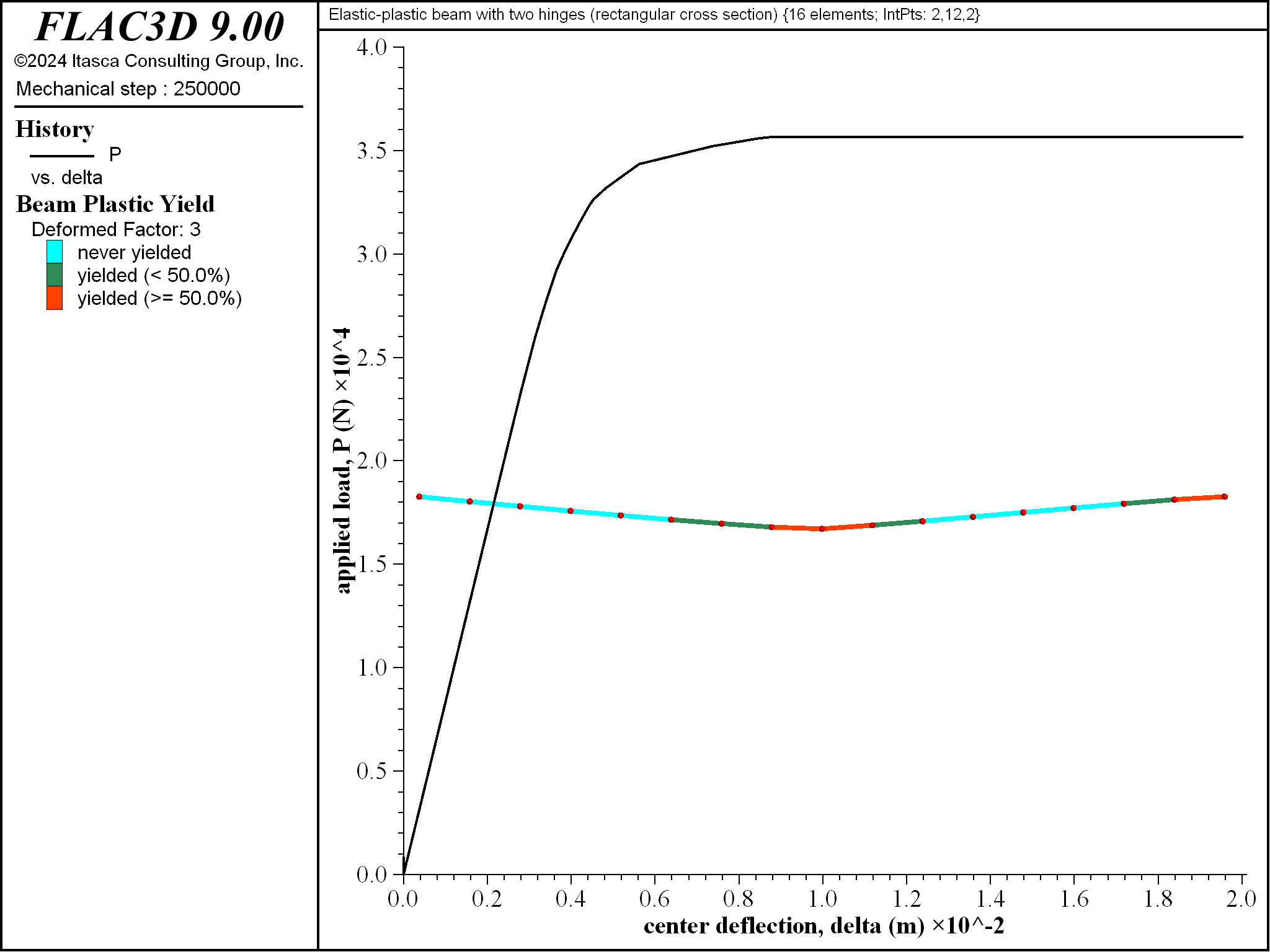
Figure 16: Progressive yielding for beam of rectangular cross section \((\Delta = 20 \textrm{ mm}\))`
The computed collapse load \((P_c)\) and yield load \((P_{yC})\) at point \(\bf C\) converge as the number of integration points through the thickness increases from 2 to 12 as shown in Figures 17 and 18. The converged values are larger than the analytical values (by 4.2 and 7.1 percent for \(P_c\) and \(P_{yC}\), respectively). The computed collapse load converges from above when using an even number of integration points, and converges from below when using an odd number of integration points. The error in \(P_{yC}\) is caused by the outermost integration points being below the surface which increases the displacement required to make those integration points begin to yield. The errors in \(P_c\) and \(P_{yC}\) are reduced to 1.4 and 4.2 percent, respectively, as the numer of elements used to model the beam is increased from 16 to 64.
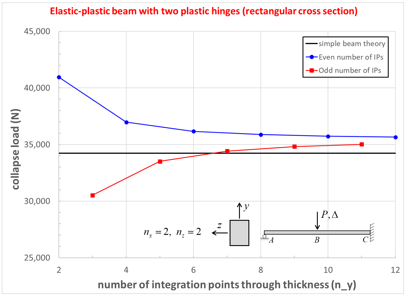
Figure 17: Collapse load convergence study for beam of rectangular cross section.
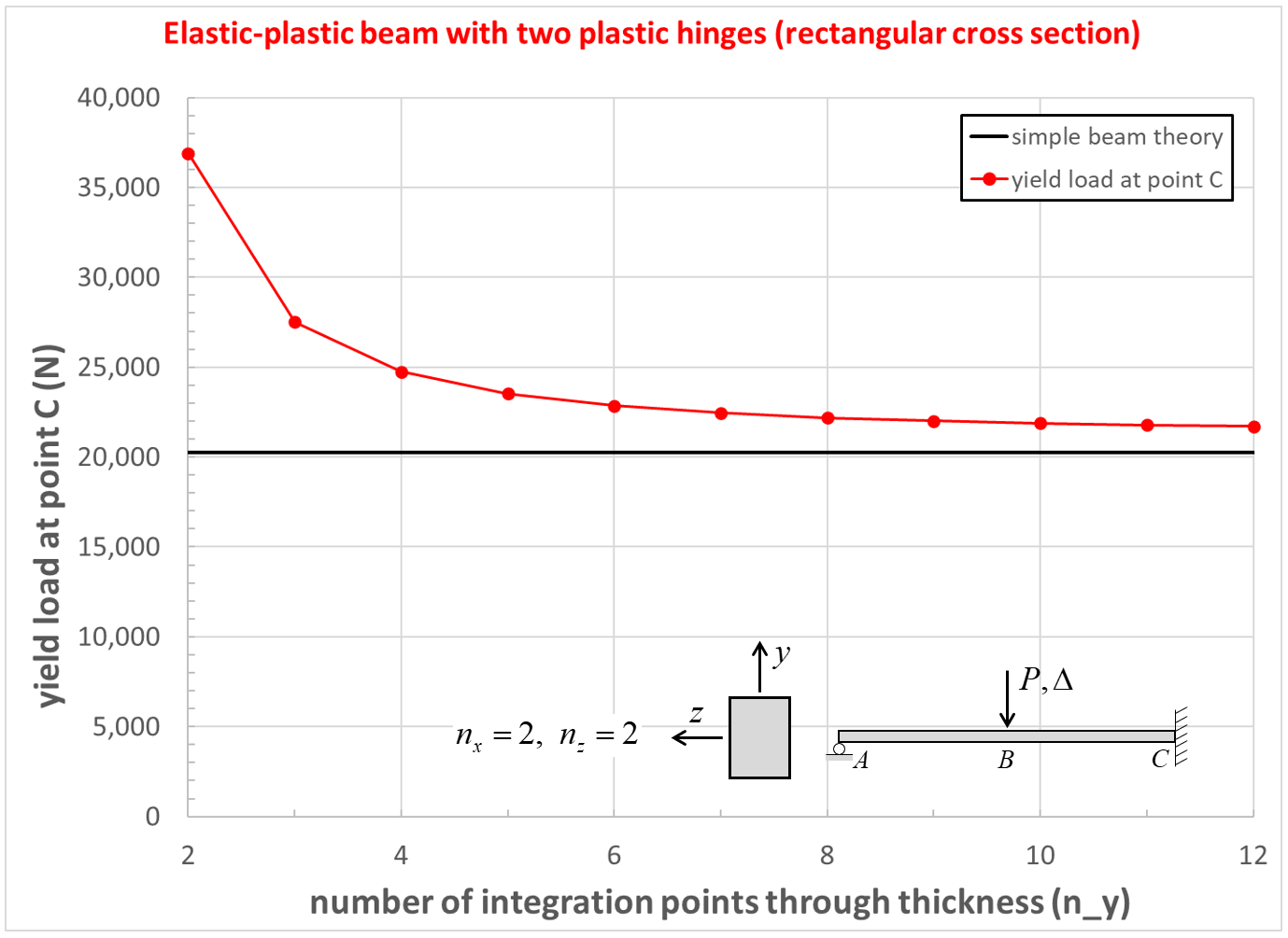
Figure 18: Yield load convergence study for beam of rectangular cross section.
Results for Plastic Beam (circular cross section)
The response for the beam of circular cross section matches the response of the analytical model (see Figure 19). The collapse load of 33317 N is within 6.6 percent of the analytical value. Hinges have formed at the center and right end. The material near point \(\bf C\) begins to yield before the material near point \(\bf B\) \((P_{yC} = 17196 \textrm{ N}\) and \(P_{yB} = 20689 \textrm{ N})\). The yielded regions expand and progress through the beam thickness to form plastic hinges at these locations when the collapse load is reached. The collapse load \((P_c)\) and yield load \((P_{yC})\) at point \(\bf C\) have errors of 6.6% and 5.1%, respectively. These errors are reduced to 0.3% and 3.2%, respectively, as the number of elements used to model the beam is increased from 16 to 64.
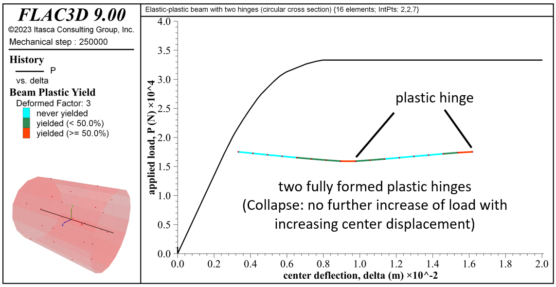
Figure 19: Load-displacement curve, final yield state, deformed shape (deformation factor: 3) and integration-point layout for the beam of circular cross section.
Results for Elastic Beam (with moment capacity)
The collapse load is also computed using a beam with an isotropic elastic constitutive model and a specified plastic moment capacity. The response is shown in Figure 20. The collapse load of 34219 N exactly matches the analytical value. Hinges have formed at the center and right end. Each hinge-formation event produces a kink in the load-displacement curve of Figure 20, and there is no prepeak softening. The yielded zones are limited to the hinge locations — the triangular-shaped yielded zones shown in Figures 1, 8 and 19 are lacking.
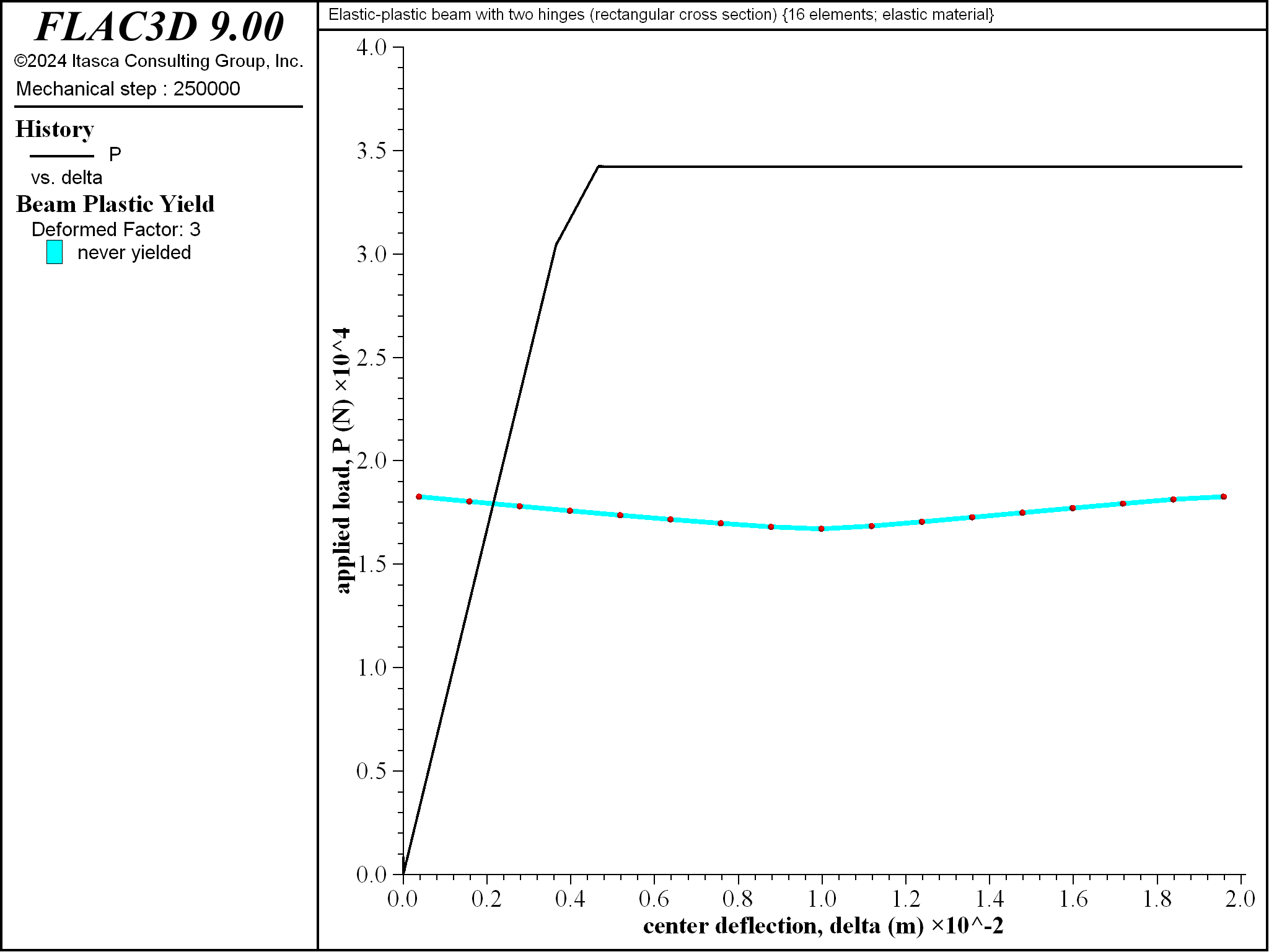
Figure 20: Load-displacement curve and deformed shape (deformation factor: 3) for the elastic beam of rectangular cross section with specified moment capacity.
References
AISC. Manual of Steel Construction, Eighth Edition. Chicago: American Institute of Steel Construction Inc. (1980).
Budynas, R. G., and A. M. Sadegh. Roark’s Formulas for Stress and Strain, Ninth Edition, New York: McGraw-Hill Education (2020).
Crandall, S.H., N.C. Dahl and T.J. Lardner. An Introduction to the Mechanics of Solids, Second Edition, New York: McGraw-Hill Book Company (1978).
Endnotes
Data Files
TwoHinges.dat
; #############################################################################
; Plastic material, rectangular cross section
model new
fish automatic-create off
[global d, b, R, ny, nz, nr, ntheta]
; =============================================================================
; Material properties and dimensions (structural steel, SI units)
  [global E  = 200e9]
  [global nu = 0.30]
  [global sigY = 250e6]
  [global XCrect = true]
  [global momCap = false] ; use moment capacity
  [global L = 1000e-3]
  [global d = 50.0e-3]
  [global b = 36.5e-3]
; Properties of mesh and integration layout
  [global nseg = 16] ; even number
  [global nx =  2]
  [global ny = 12]
  [global nz =  2]
; =============================================================================
program call 'support'
program call 'TwoHinges-setup'

model save 'rect_delta=0'
[deltaDot = 8.0e-8]
[pushDown( 0.5e-3, 20.0e-3, false )]

; #############################################################################
; Plastic material, circular cross section
model new
fish automatic-create off
[global d, b, R, ny, nz, nr, ntheta]
; =============================================================================
; Material properties and dimensions (structural steel, SI units)
  [global E  = 200e9]
  [global nu = 0.30]
  [global sigY = 250e6]
  [global XCrect = false]
  [global momCap = false] ; use moment capacity
  [global L = 1000e-3]
  [global R = 25.0e-3]
; Properties of mesh and integration layout
  [global nseg = 16] ; even number
  [global nx = 2]
  [global nr = 2]
  [global ntheta = 7]
; =============================================================================
program call 'support'
program call 'TwoHinges-setup'

model save 'circ_delta=0'
[deltaDot = 8.0e-8]
[pushDown( 0.5e-3, 20.0e-3, false )]

; #############################################################################
; Elastic material with moment capacity, rectangular cross section
model new
fish automatic-create off
[global d, b, R, ny, nz, nr, ntheta]
; =============================================================================
; Material properties and dimensions (structural steel, SI units)
  [global E  = 200e9]
  [global nu = 0.30]
  [global sigY = 250e6]
  [global XCrect = true]
  [global momCap = true] ; use moment capacity
  [global L = 1000e-3]
  [global d = 50.0e-3]
  [global b = 36.5e-3]
; Properties of mesh and integration layout
  [global nseg = 16] ; even number
  [global nx =  2]
  [global ny = 12]
  [global nz =  2]
; =============================================================================
program call 'support'
program call 'TwoHinges-setup'

model save 'rectElas_delta=0'
[deltaDot = 8.0e-8]
[pushDown( 0.5e-3, 20.0e-3, false )]
TwoHinges-setup.dat
; =============================================================================
; Create mesh, assign beam properties and boundary conditions, apply load.
structure beam create by-line (0,0,0) ([L],0,0) segments [nseg]
[setBeamProperties( momCap )]

; Simple support at left end, fully fixed at right end
structure node fix velocity-y range group 'Beam Begin'
structure node fix velocity-x velocity-y rotation-z range group 'Beam End'
structure node group 'ctrNode' range position-x [0.5*L]
structure node fix velocity-y range group 'ctrNode' ; midpt velocity to be applied

; Get component-ids of elem just to right of center, and at right end.
[elemRtB_CID   = struct.id.component(  struct.near( vector(1.01*0.5*L, 0, 0) ) )]
[elemLeftC_CID = struct.id.component(  struct.near( vector(     L, 0, 0) ) )]
structure beam history name 'momentAtB' moment-z component-id [elemRtB_CID] end 1
structure beam history name 'momentAtC' moment-z component-id [elemLeftC_CID] end 2

fish history name 'P' Pa
fish history name 'delta' delta
fish callback add updateDelta  -1.0  ; start of step
fish callback add yieldMonitor -1.0 interval 10  ; start of step

model large-strain false
structure mechanical damping combined-local
| Was this helpful? ... | Itasca Software © 2024, Itasca | Updated: Nov 12, 2025 |
