Elastic Beam (Plastic Hinges)
Problem Statement
Note
To view this project in FLAC3D, use the menu command . The main data files used are shown at the end of this example. The remaining data files can be found in the project.
This example demonstrates two methods, referred to as the single- and double-node methods, by which one can model the initiation and subsequent behavior of a plastic hinge in a beam. The single-node method involves specifying the limiting plastic moment (via the plastic-moment property of the beam) that can be carried by the elements making up the beam. The double-node method involves creating double nodes at each potential hinge location, and then appropriately linking these nodes together. The strengths and limitations of each method are discussed in Plastic Hinge Formation (with beam elements).[1]
Analytical Solution
A statically indeterminate beam of length \(2 l\) is loaded with a distributed load \(w\). This load corresponds to the self-weight of the beam. Assuming the beam can support a maximum bending moment, \(M^{pl}\) (after which a plastic hinge forms, and the section deforms indefinitely at constant load), the problem involves finding the maximum load, \(w^{max}\), that produces a kinematic mechanism and, consequently, the collapse of the system. The problem is illustrated in Figure 1. This problem can be solved using the plastic theory of structures (see, for example, Riley and Zachary, 1989, pp. 581-586). According to this theory, the development of plastic hinges is dictated by the occurrence of maximum bending moments.
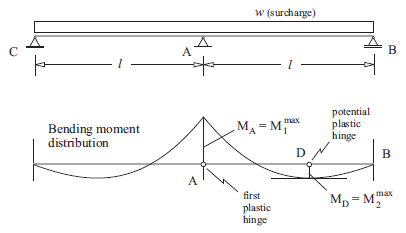
Figure 1: Bending moment distribution in a statically indeterminate continuous two-span beam.
The lower part of Figure 1 displays the bending moment distribution for the continuous two-span beam assuming elastic behavior. The maximum moment occurs at the position \(A\), indicated as \(M_A=M_1^{max}\) in the figure. A second maximum moment occurs at point \(D\) and is indicated as \(M_D=M_2^{max}\). (Note that for the given symmetric problem geometry, there is another point \(D\)—not indicated in the figure—between points \(C\) and \(A\).)
Consider a gradually increasing surcharge, \(w\), acting on the beam. If the maximum plastic moment that the beam supports is \(M^{pl}\), the first plastic hinge will develop at the point where \(M^{pl}\) is reached first (i.e., at point \(A\)). After the first hinge has formed, the problem is still stable. The system behaves as two separate beams with a constant bending moment \(M^{pl}\) at point \(A\). Collapse of the system will occur when a second hinge develops (i.e., at point \(D\) where the second maximum bending moment occurs). This is because a second hinge at position \(D\) creates a kinematic mechanism.
The location of the point \(D\) in Figure 1, where the second plastic hinge develops, can be found from simple beam theory analysis as described here. Consider the simply supported beam shown in Figure 2. This represents the situation after the first plastic hinge has developed at the midpoint in Figure 1. The bending moment at point \(A\) is constant and equal to \(M^{pl}\). Figure 2 also illustrates the distribution of bending moments \(M(x)\) and shear force \(Q(x)\) along the right span of the beam. The objective, then, is to find the coordinate, \(x_D\), of the maximum bending moment where the second plastic hinge that produces collapse will develop.
The reaction force at point \(B\) is obtained from the condition of equilibrium of moments at point \(A\), i.e.,
The distribution of shear force, \(Q(x)\), is given by
The distribution of bending moment, \(M(x)\), is given by
The coordinate \(x_D\) can be found from the preceding expressions and the condition \(Q(x_D)=0\)
The maximum surcharge \(w^{max}\) is found from the condition \(M(x) = M^{pl}\) at \(x=x_D\)
By application of these equations, the position of the second plastic hinge, \(x_D\), and the maximum load, \(w^{max}\), can be determined. The results are
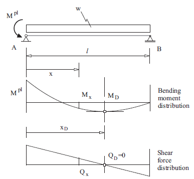
Figure 2: Bending-moment and shear-force distribution in the right-half of the two-span beam after a plastic hinge has developed at point A.
FLAC3D Model
The particular problem to be considered is defined as follows:
Plastic hinge formation by single-node method
We set the plastic-moment property of the beam equal to the limiting plastic moment. Only the right span of the two-span beam is modeled. It is discretized into 20 elements of length 0.5 m each (see Figure 3). The beam contains 21 nodes, and each node has a limiting plastic moment of \(50 \textrm{ MN}\,\textrm{m}\).
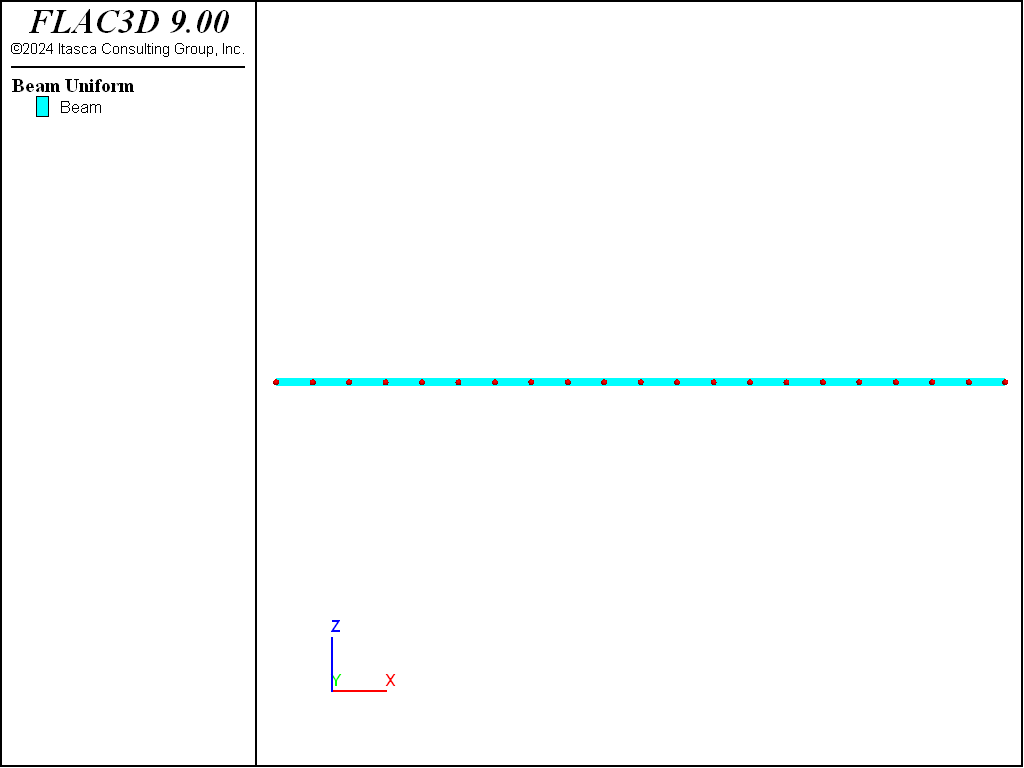
Figure 3: Geometry of the FLAC3D model of the right span of the two-span beam showing mesh with nodes and global coordinate system.
Plastic hinge formation by double-node method
We create double nodes at the locations having the potential for a plastic hinge to develop. Only the right span of the two-span beam is modeled. It is discretized into 20 elements of length 0.5 m each (see Figure 3). Each element is defined by two nodes (by using the distinct keyword of the structure beam create command); thus, the beam has 40 nodes. The nodes of adjacent elements are linked together using the structure node join command. There are 19 links (i.e., all nodes except the extreme nodes in Figure 3 are linked, and each pair of nodes is joined by a link). The limiting plastic moment is assigned to the links by first changing the link conditions with the structure link attach command, and then setting both the compressive and tensile yield strengths equal to the desired plastic-moment capacity of \(50 \textrm{ MN}\,\textrm{m}\).
Applying a uniform surcharge in both methods
The uniform surcharge \(w\) is applied as a distributed load with the structure beam apply command. This is done in the FISH function find_critical_load by incrementing the FISH variable load from 5.5 to 6.6 in 0.05 increments. The maximum surcharge is determined by finding the load for which static equilibrium cannot be obtained using the model solve command for which cycling is continued until either the local unbalanced force ratio falls below \(1 \times 10^{-5}\) or 100,000 steps are taken. If static equilibrium has not be obtained for a given load after 100,000 steps, then it is assumed that a kinematic mechanism has developed. A save file is created at the end of each load stage.
Results and Discussion
For both the single- and double-node methods, a kinematic mechanism develops for a load of 5.85 MN/m. The last stable case is for a load of 5.80 MN/m. These results bound the value of 5.83 MN/m from the analytical solution. The bending-moment and shear-force distributions before collapse are contained in the “doublenode_580” save file, and are shown in Figures 4 and 5. The location of the failed hinge can be seen by plotting the link yield state indicators of the \(y\)-rotation degree-of-freedom as shown in Figure 6. Because only one node of each node pair has a link, the side of the element connected to the other node will display the “No Link” state. The plastic hinge develops at link 12 (with link numbering starting at 1 on the left end of the beam). Each element has a length 0.5 m; thus, the failed link is located at a distance of 6 m from the left end. This agrees well with the analytical solution of 5.86 m. The plastic hinge for the single-node model can be observed by plotting the deformed shape in Figure 7, and noting that the bending-moment magnitude at the plastic hinge location is \(50 \textrm{ MN}\,\textrm{m}\).
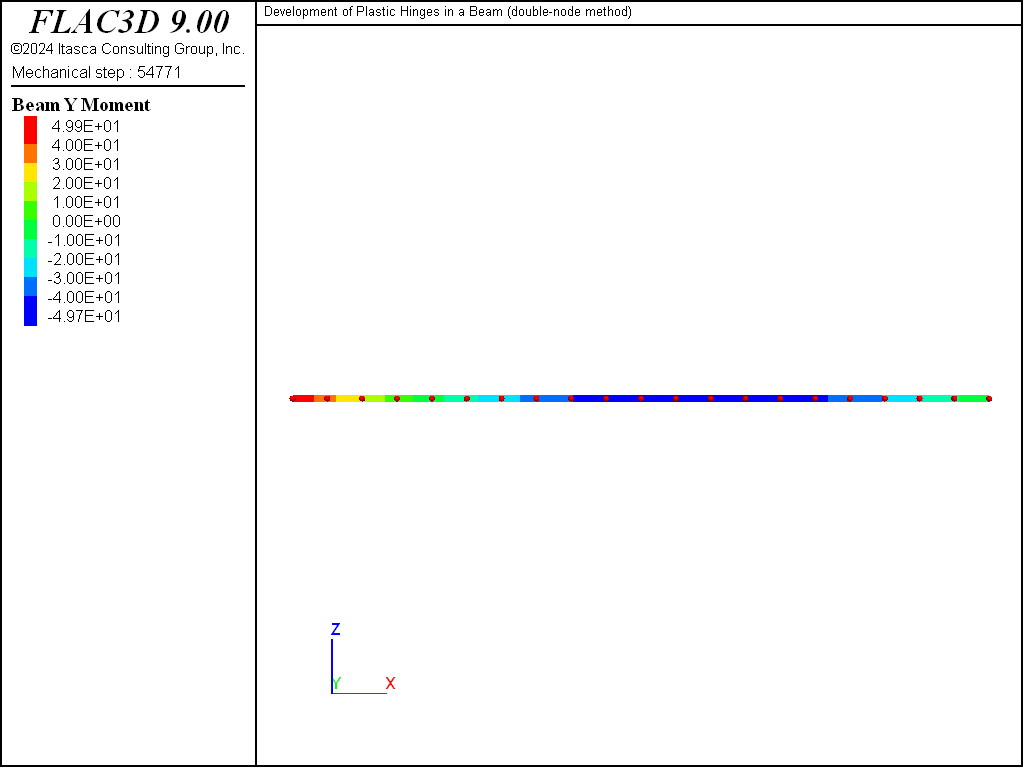
Figure 4: Bending-moment distribution before failure (double-node approach, w = 5.80 MN/m).
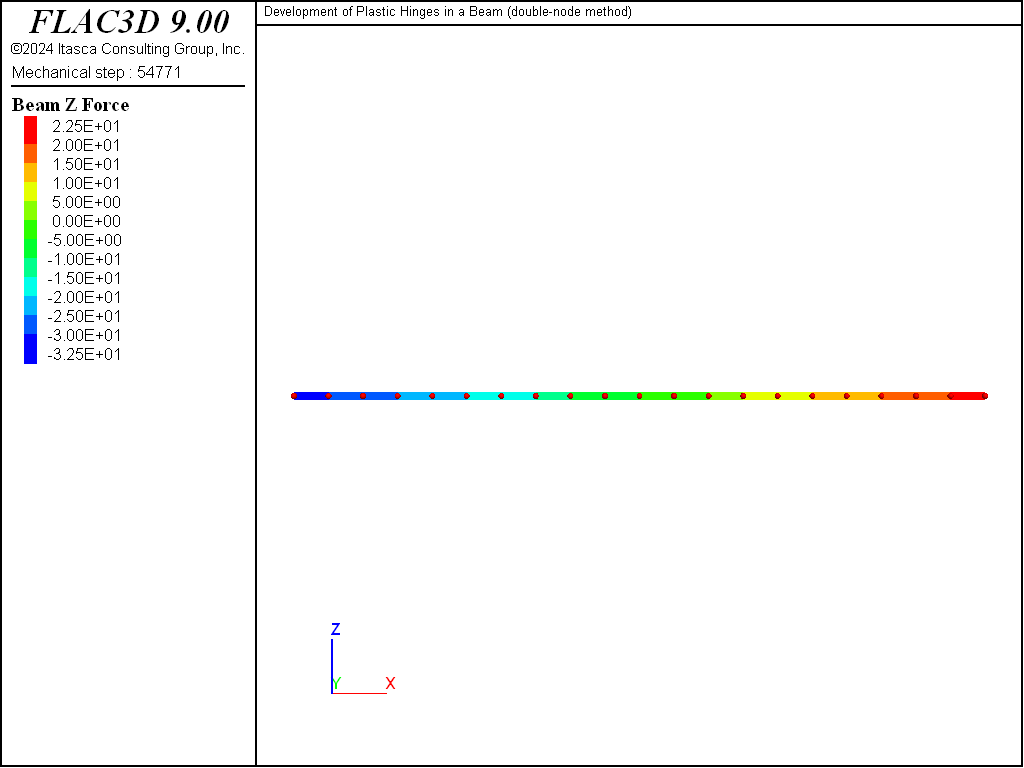
Figure 5: Shear-force distribution before failure for (double-node approach, w = 5.80 MN/m).
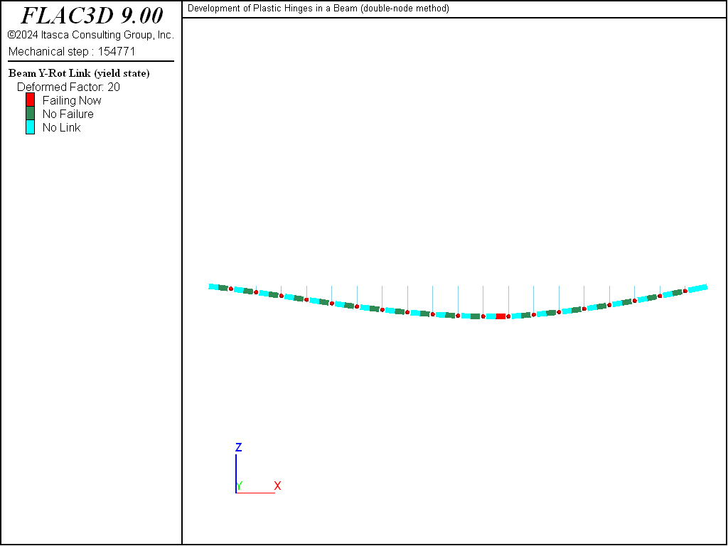
Figure 6: Deformed shape (deformation factor: 20) with link yield state, nodes as red dots and links as blue sticks (double-node approach, w = 5.80 MN/m).
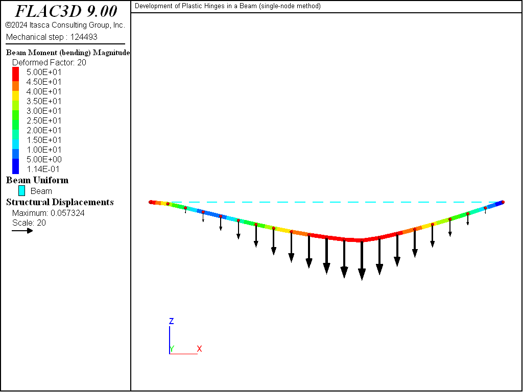
Figure 7: Deformed shape (deformation factor: 20), undeformed shape and contour of bending-moment magnitude (single-node method).
Reference
Riley, W. F. and L. Zachary. Introduction to Mechanics of Materials. New York: John Wiley & Sons Inc. (1989).
Endnote
Data Files
plastic-moment.dat
model new
fish automatic-create off
model large-strain off
model title 'Development of Plastic Hinges in a Beam (single-node method)'
;
structure beam create by-line (0,0,0) (10,0,0) segments 20 ...
                   element-type euler-bernoulli
; Give group names to external nodes.
structure node group 'Begin' range position-x  0.0
structure node group 'End'   range position-x 10.0
; Assign beam properties.
structure beam property young 210e3 poisson 0.3
structure beam property cross-sectional-area 1.0 moi-y 0.083 moi-z 0.083 ...
                     torsion-constant 1.25e-4 plastic-moment 50.0 ...
                     direction-y (0,1,0)
; Assign boundary conditions for external nodes.
structure node fix velocity rotation-x rotation-z range group 'Begin'
structure node fix velocity-y velocity-z rotation-x rotation-z range group 'End'
; Apply bending moment at left end.
structure node apply moment (0,-50,0) range group 'Begin'

model history mechanical ratio-local
;
fish define find_critical_load
    loop global load (5.5,6.5,0.05) ; Load is global so you can see
                                    ; progress in the FISH browser
        local starting_cycles = mech.step
        global filename = 'plasticmoment_' + string(load*100)
        command
            history purge
            structure beam apply (0,[-load])
            model solve ratio-local 1e-5 or cycles 100000
            model save [filename]
        end_command
        local solve_cycles = mech.step - starting_cycles
        local line = 'STABLE'
        if solve_cycles >= 100000
            line = 'UNSTABLE (maximum steps reached)...'
        else if load > 6.5
            line = 'STABLE and LAST'
        end_if
        io.out(line)
        if line # 'STABLE'
            exit loop
        end_if
    end_loop
end
[find_critical_load]
model save 'plasticmoment_final'
double-node.dat
model new
fish automatic-create off
model large-strain off
model title 'Development of Plastic Hinges in a Beam (double-node method)'

; Create the beam using the {distinct} keyword: elements do not share nodes.
structure beam create by-line (0,0,0) (10,0,0) segments 20 distinct ...
                   element-type euler-bernoulli
; Give group names to external nodes.
structure node group 'Begin' range position-x  0.0
structure node group 'End'   range position-x 10.0
; Assign beam properties.
structure beam property young 210e3 poisson 0.3
structure beam property cross-sectional-area 1.0 moi-y 0.083 moi-z 0.083 ...
                     torsion-constant 1.25e-4 ...
                     direction-y (0,1,0)
; Assign boundary conditions for external nodes.
structure node fix velocity rotation-x rotation-z range group 'Begin'
structure node fix velocity-y velocity-z rotation-x rotation-z range group 'End'
; Create links and set their conditions and properties.
structure node join
structure link attach rotation-y normal-yield
structure link property rotation-y stiffness 3.0e6 ...
                     yield-tension 50.0 yield-compression 50.0
; Apply bending moment at left end.
structure node apply moment (0,-50,0) range group 'Begin'

model history mechanical ratio-local
; FISH function to keep increasing applied load till plastic failure.
fish define find_critical_load
    loop global load (5.5,6.5,0.05) ; Load is global so you can see
                                    ; progress in the FISH browser
        local starting_cycles = mech.step
        local filename = 'doublenode_' + string(load*100)
        command
            history purge
            structure beam apply (0,[-load])
            model solve ratio-local 1e-5 or cycles 100000
            model save [filename]
        end_command
        local solve_cycles = mech.step - starting_cycles
        local line = 'STABLE'
        if solve_cycles >= 100000
            line = 'UNSTABLE (maximum steps reached)...'
        else if load > 6.5
            line = 'STABLE and LAST'
        end_if
        io.out(line)
        if line # 'STABLE'
            exit loop
        end_if
    end_loop
end
[find_critical_load]
model save 'doublenode_final'
| Was this helpful? ... | Itasca Software © 2024, Itasca | Updated: Nov 12, 2025 |
