Plastic Flow in a Punch Problem (FLAC2D)
Problem Statement
Note
The project file for this example is available to be viewed/run in FLAC2D.[1] The main data file used is shown at the end of this example.
Difficulties are sometimes reported in the modeling of plastic flow where large velocity gradients exist. The use of interfaces embedded within a continuum finite-element mesh (e.g.,Van Langen and Vermeer 1991) has been suggested at locations where singular behavior is expected. The velocity field at the corners of a punch driven into a cohesive, frictionless soil is shown to be discontinuous. Figure 1 shows the problem geometry and boundary conditions. This example is used to demonstrate that FLAC2D can produce accurate results without introducing interfaces, provided that the expected singular point is not located at a gridpoint. One reason for avoiding interfaces is that, for some cases, the internal rupture surfaces may be unknown in advance.
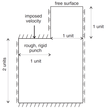
Figure 1: Boundary conditions and dimensions for the numerical simulation of a punch problem.
FLAC2D Model
Figure 2 shows the grid used for the simulation. There are eight zones and nine nodes under the punch. The properties of the material are as follows.
bulk modulus (\(K\)) |
1.66667 MPa |
shear modulus (\(G\)) |
1.0 MPa |
density (\(p\)) |
1000 kg/m3 |
cohesion (\(c\)) |
10 kPa |
friction angle (\(φ\)) |
0◦ |
A velocity loading condition, shown in Figure 3, is applied. The gradual application of the boundary velocity reduces the tendency for initial oscillation in the loading curve, but does not affect the collapse load.
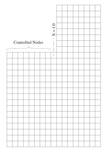
Figure 2: FLAC2D grid for 8-zone punch.
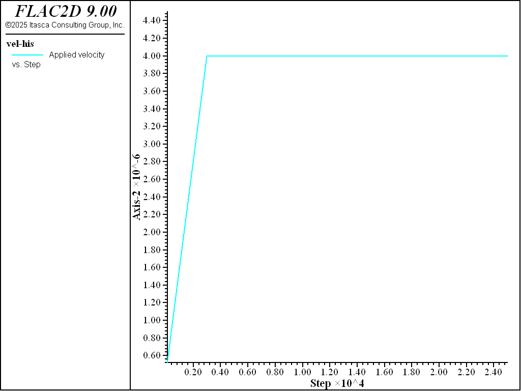
Figure 3: Applied punch velocity.
Results and Discussion
The FISH function load calculates the numerical and analytical values of pressure beneath the punch. Note that for the numerical simulation, the total pressure is taken as the sum of vertical forces on the velocity-controlled nodes, divided by the width of the punch (unity, in this case). The width of the punch extends to one-half the zone at which the velocity jump occurs. The load is normalized by dividing by the cohesion, \(c\), and the displacement is normalized by multiplying by the factor \(G/c\). The resulting normalized load/displacement curve is given in Figure 4, and the steady-state velocity field is given in Figure 5. The numerical value calculated for the steady state load is 5.147 \(c\), which is only 0.11% in error of the exact load of \((2 + π)c\). The pattern of shear strain rate is illustrated in Figure 6. The observed collapse mechanism is defined quite well, even for a material that does not soften.
Figure 4: Normalized load/displacement for 8-zone punch.
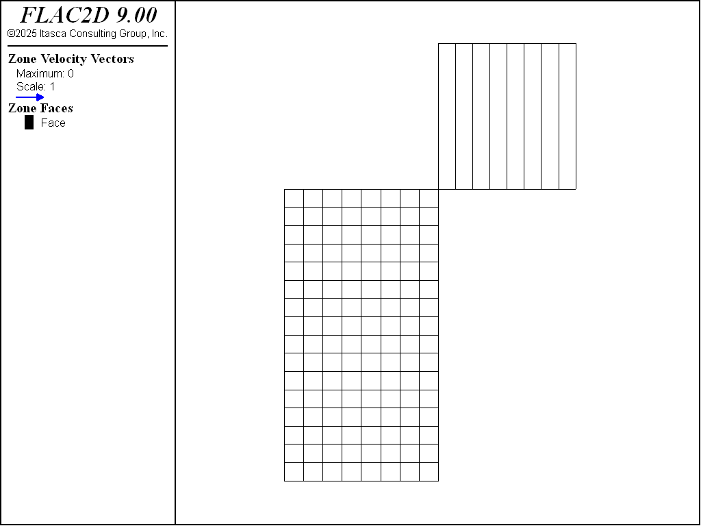
Figure 5: Steady-state velocity field for 8-zone punch.
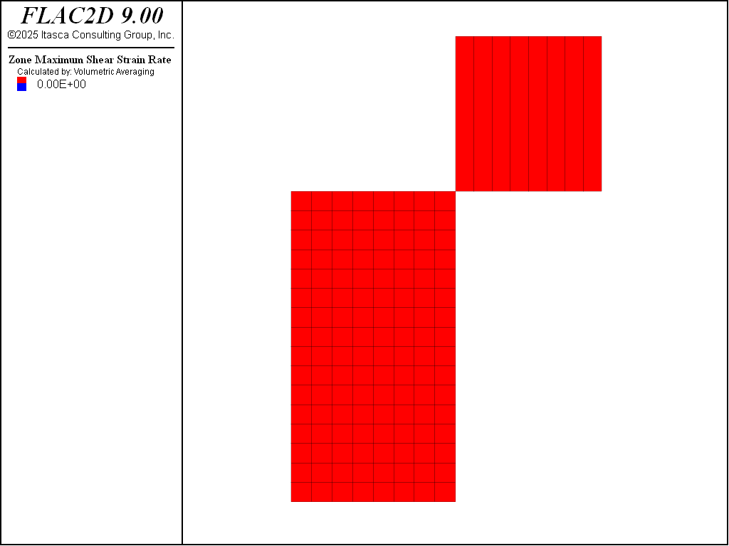
Figure 6: Contours of maximum shear strain rate for 8-zone punch.
Reference
Van Langen, H., and P. A. Vermeer. “Interface Elements for Singular Plasticity Points,” Int. J. Num. Anal. Methods Geomech., 15, 301-305 (1991).
Data Files
punch.dat
;
;Plastic Flow in a Punch Problem
;
;---------------------------------------------------------------------
model new
model large-strain off
model configure

; Create zones
program call 'geometry'

; Assign constitutive model and properties
zone cmodel assign mohr-coulomb
zone property bulk 1.67e6 shear 1.e6 cohesion 1.e4 density 1000
zone property tension 1.e10

;boundary conditions
zone face skin
zone gridpoint fix velocity-x range group 'West1'
zone gridpoint fix velocity-x range group 'West2'
zone gridpoint fix velocity-x range group 'East'
zone face apply velocity (0,0) range group 'Bottom'
zone face group 'load' range group 'Top2' position-x 0 1
zone face apply velocity (0,0) range group 'load'

[pnt = list(gp.list)(gp.isgroup(::gp.list,"load"))]

; measure load on moving plate
fish define load
    local sum = 0.0
    sum = -1.0*list.sum(gp.force.unbal(::pnt)->y)
    local cohesion = zone.prop(zone.head,'cohesion')
    local shear = zone.prop(zone.head,'shear')
    load = sum / cohesion
    local pnt = gp.near(0,2)
    global _disp = -gp.disp.y(pnt)*shear/cohesion
    global analyt = (2.0+math.pi)
end

; gradual increase in starting velocity
fish define ramp
    while_stepping
        if global.step <= 3000 then
            local  ud_app = 4.0e-7 + global.step *3.6e-6/3000
            global vel_his = ud_app
            gp.vel(::pnt)->y = -ud_app
        end_if
end

fish history load
fish history analyt
fish history _disp
fish history vel_his
model history mechanical ratio
history interval 100
model step 25000
model save 'punch'
Endnote
| Was this helpful? ... | Itasca Software © 2024, Itasca | Updated: Nov 12, 2025 |
