Block Quality Metrics
Most of the problems that occur when running 3DEC models are the result of bad block geometries. 3DEC offers the ability to cut up blocks to any angle at any size. This is a very powerful feature. This power, however, also allows creation of very thin or very small blocks. These can cause problems when deformation occurs (in large strain) and blocks start to collapse, resulting in error messages such as “negative volume zone” or “bad face normal.”
The first step in dealing with these problems is identifying the bad blocks. The several ranges listed are useful for locating bad blocks.
This range selects blocks with a volume within the specified lower and upper limits. This is useful for identifying very small blocks.
This range selects blocks with a minimum edge length between the specified upper and lower limits. This is useful for identifying blocks that may not have small volumes but may have very small edges — which makes them difficult to zone.
This range selects blocks with a maximum aspect ratio between the specified upper and lower limits. The aspect ratio is defined as the maximum edge length divided by the cube root of the volume. Generally, blocks with high aspect ratios (> 10) are difficult to zone and may cause numerical problems as they deform. Sometimes it is possible to cut these long, thin blocks to create an assembly of shorter blocks with better aspect ratios.
This range selects blocks with a minimum face area between the specified upper and lower limits. Similar to the edge-length range, this helps identify blocks that may not be small, but may have very small faces.
range concave
This range selects blocks that are concave. Some cutting operations in 3DEC may result in blocks that are slightly concave. These blocks can generally still be zoned and, generally, will still work. However, the contact detection and force calculation may not be accurate for concave faces.
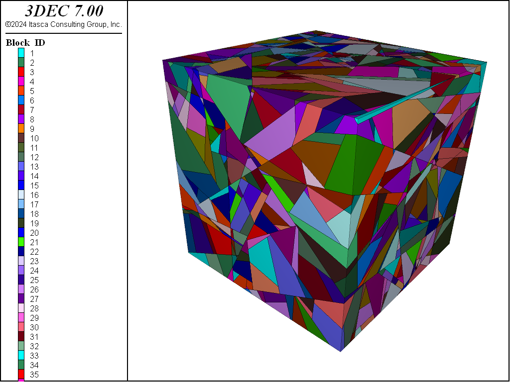
An example of using these ranges is shown below. A discrete fracture network (DFN) is created and used to cut a large block. This results in some blocks with bad geometries.
model new
model random 10000

model domain extent -50 50 -50 50 -50 50

; -- Generate DFN --
fracture template create 'dfn_template' size power-law 3 size-limits 1 100
fracture generate template 'dfn_template' dfn '99' mass-density 0.1

; create block
block tolerance 0.001
block create brick -20 20 -20 20 -20 20
block cut dfn name '99'
;
; --- find and group bad blocks ---
;
block group 'bad_face' slot '1' range face-area 0 0.0001

block group 'bad_edge' slot '2' range edge-length 0 0.005

block group 'bad_aspect' slot '3' range aspect-ratio 10 1000

block group 'bad_volume' slot '4' range volume 0 0.001
It is ideal to cut the model in such a way that these bad blocks do not form. However if this is not possible, the techniques shown here can be used to identify bad blocks. Once identified, blocks with bad geometries can often be deleted if running in large strain. This is not advised if running in small strain because it will leave gaps in the model that will not close.
If the bad blocks zone successfully, they can be made elastic to prevent spurious plastic deformations. If they do not zone, they can be left as rigid.
| Was this helpful? ... | 3DEC © 2019, Itasca | Updated: Feb 25, 2024 |

