Structural Finite Elements
This section describes a finite element formulation which can be used to model tunnel liners and other structures attached to 3DEC blocks (such as dams). Its implementation within the explicit solution scheme used by 3DEC, and the logic that was developed to handle the contact between the special FE blocks and the standard 3DEC blocks, are also presented. The input commands and keywords added to 3DEC in order to read or generate the FE block mesh and assign material models and properties are explained.
Element Formulation
The new module creates special blocks (FE blocks) that can be added to a 3DEC model composed of standard polyhedral deformable blocks. The new FE blocks consist of a finite element mesh composed of three-dimensional brick elements with 20 nodes. The element formulation, presented in this section, follows the standard methodology found in finite element texts (Hughes 1987).
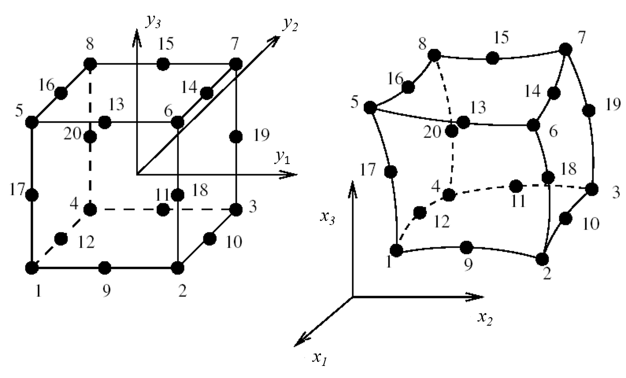
The geometry of isoparametric finite elements is described by the mapping of a master cubic element into the actual element shape, as shown in Figure 3.5 ← this figure appears to have never existed, which also indicates the node numbering convention adopted. For the case of the 20-node brick element, the edges are defined by parabolic segments.
Notation Conventions
Uppercase subscripts, such as \(I\), denote element nodes ranging from 1 to 20. Lowercase subscripts, such as \(j\) , \(k\), and \(m\), denote coordinate directions and range from 1 to 3. Summation on repeated indices is implied.
Geometry Mapping
The geometry of the master element (a cube with 8 nodes placed at the corners and 12 nodes at the edge midpoints) is defined in the \(y\)-coordinate system, with values ranging from −1 to 1, as indicated in Figure 1.
The coordinates of a generic point of the master element are denoted by
while the corresponding point in the transformed element is
and the coordinates of node \(I\) of the element are
The element geometry mapping is governed by
which expresses the coordinates, \(x\), of a generic point as a sum of products of the nodal shape functions, \(N_I\), function of the natural coordinates, \(y\), and the nodal coordinates, \(x_I\).
The Jacobian matrix of the transformation is given by
and its inverse, evaluated numerically, is
The expressions of the shape functions, \(N_I\), and their derivatives with respect to the master element coordinates, \(\partial/\partial y_m (N_I)\), are given in later discussion (see the topic “Shape Functions and Derivatives”).
Displacements and Strains
The displacement field of isoparametric elements is governed by an expression similar to the geometry mapping Equation (1).
where the generic displacement vector at point \(y\) is
and the displacement vector of element node \(I\) is
In order to derive the expressions of the strains, defined as
the derivatives of the displacement field must be calculated from Equation (2),
The derivatives of the shape function in the global coordinates are obtained by application of the chain rule:
The components of the strain tensor are grouped more conveniently in vector form:
Then, after introducing Equations (3) and (4) in (5), and setting the result in matrix form, the strains may be expressed as
where the strain-displacement matrix for node \(I\) is given by
Stresses and Nodal Forces
As the force-displacement relations for the element cannot be expressed in closed form, numerical integration has to be used. The element strains and stresses are evaluated at the Gauss integration points of the element. Once the strains (and strain increments) are obtained from Equation (6), the application of the assumed constitutive model produces the new stresses. Formally,
where the stresses are arranged in vector form,
The nodal force vector at node \(I\), equivalent to a given state of stress, is
and is calculated as
The integration, extending to the element volume, is performed numerically as a summation of the values of the integrand at the Gauss points — i.e.,
where \(V_G\) are the elementary volume terms obtained from the Jacobian matrix of the geometry transformation, and \(W_G\) are the standard Gauss point weights (Hughes 1987). In the present implementation, 2 × 2 × 2 or 3 × 3 × 3 Gauss points may be used. The former corresponds to reduced integration, and, in some cases of unconstrained systems, may allow spurious mechanisms. However, since it is faster, and the stresses at the location of the 2 × 2 × 2 Gauss points tend to be more accurate, it is taken as the default option.
Gravity Forces
The nodal forces equivalent to a body force
are given by
which are also evaluated numerically.
Concentrated Forces
Concentrated forces, such as point contact forces applied on the element faces, originate nodal forces given by, for node \(I\),
where the shape function is evaluated at the point of application of the force
Element Implementation in 3DEC
The implementation of the 20-node brick element was designed to allow a smooth integration of the special blocks into the 3DEC logic. In particular, the new blocks were intended to be compatible with the essential aspects of the contact logic, the solution algorithm and the graphical routines, as described in the following sections.
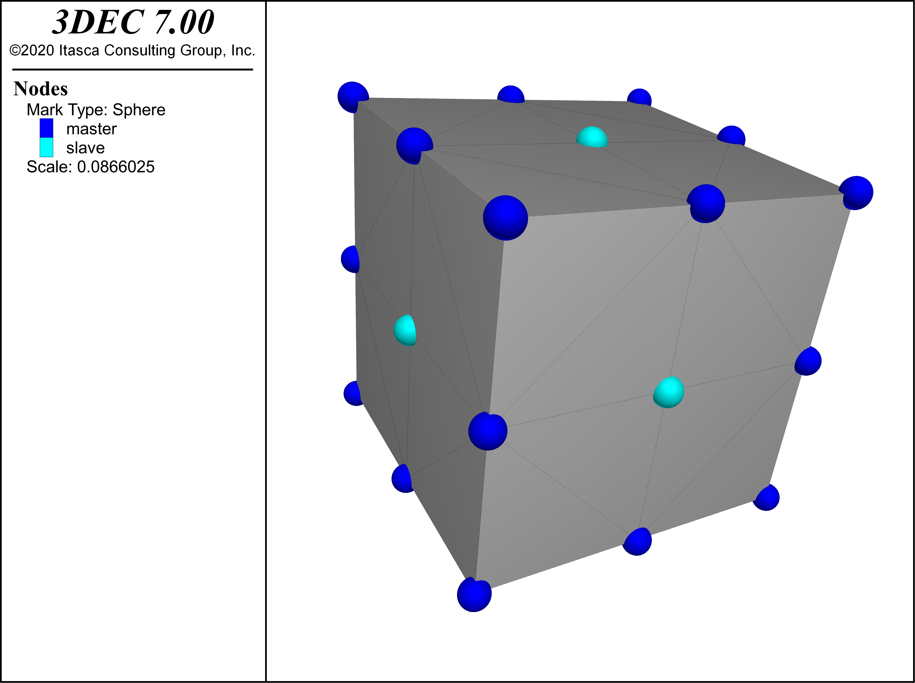
The standard deformable blocks in 3DEC have a polyhedral form, with an internal tetrahedral mesh, leading to an outer surface defined by triangular faces. The contact logic and the graphical representation are based on triangulated surfaces. In general, the surface of the 20-node brick is curved, which would require a different, and computationally much more expensive, treatment of the geometric contact calculations. Therefore, in order to allow the special FE blocks to be handled by the same routines, it was decided to approximate the block external boundary by means of a polyhedral surface composed of triangles. As shown in Figure 2, eight triangular faces are used to approximate each face of the brick.
In 3DEC, graphical representation of displacements and stresses in block cross-section assumes a discretization into tetrahedral zones. To make these routines usable with 20-node bricks, a simple scheme was devised, based on a fictitious discretization of each element into tetrahedra. Each element is divided into 8 sub-bricks, using extra nodes placed at the middle point of faces (as shown in Figure 2), and another node at the center of the element. Each sub-brick is then divided into 6 tetrahedra, in an arrangement compatible with the triangular face approximation discussed above. For the purpose of graphical representation, the tetrahedral zones are assigned a stress state corresponding to the nearest Gauss point.
This scheme requires extra nodes in the element: six mid-face nodes and one central node. These are treated as slave nodes, with velocities and displacements obtained from the 20 master nodes, using the assumed deformation field (see Equation (1)). The \(y\)-coordinates of the slave nodes are listed in the section “Shape Functions and Derivatives.”
Contact Forces
The nodes of the element, either master or slave, perform the same functions as zone gridpoints, and are similarly treated as vertices for contact purposes. Therefore, the standard 3DEC contact logic is used, based on sub-contacts located at vertex-to-face and edge-to-edge interaction locations.
The FE block displacements at the sub-contacts are evaluated assuming the approximated triangulated surface, and are therefore obtained from the gridpoint displacements in the same way as for the polyhedral blocks. The contact forces that are applied to the slave node at the center of the brick faces must be transferred to the master nodes using Equation (9).
The common-plane logic that is used in 3DEC in the contact detection routines assumes that blocks are convex. If FE blocks are non-convex, then no contact is detected in the concave portion of their surface. If a concave face must be in contact with other blocks, then it is necessary to divide the FE block into convex blocks, which may be joined to behave as a monolithic block, as is done with regular blocks.
Application of Boundary Loads and Velocities
External loads applied with the boundary command are also applied to FE blocks, based on the triangulated boundary. The loads applied at the slave nodes are automatically transferred to the master nodes using Equation (9), as in the case of the contact forces. The only difference with respect to the regular blocks is in the treatment of gravity loads which must be introduced by means of Equation (5).
Fixed displacement conditions are applied in 3DEC by prescribing gridpoint velocities using the boundary command. This procedure is also used for FE nodes.
Solution Algorithm
The solution procedure in 3DEC is based on an explicit timestepping algorithm that integrates the nodal equations of motion. The same procedure is used for dynamic and quasi-static analysis. In the latter case, high damping values are introduced to obtain convergence to static equilibrium or to a failure mechanism. In the case of deformable blocks, discretized into zones or elements, the equations of motion of each gridpoint are integrated. The FE blocks are treated in the same way — i.e., for a given node \(I\), the equations of motion may be expressed as
where \(m\) is the nodal mass, \(\alpha\) is the viscous damping parameter and \(F_I\) is the nodal force vector. The nodal forces are calculated as a sum of four components:
where:
The calculation of the timestep required for numerical stability is based on the fictitious discretization of the element into zones. Since the assemblage of these zones is known to behave in a stiffer manner than the actual 20-node brick, this approximation provides a safe estimate. For static analysis, the mass scaling procedure gives the gridpoint masses. For dynamic analysis, the tetrahedral mesh is still used to give the gridpoint masses, in such a way that the total element mass is preserved. More accurate schemes exist to provide a diagonal mass matrix for these types of isoparametric elements (Hughes 1987), as explicit solution methods do not permit the use of the consistent mass matrices derived from the standard element formulation.
Generation and Use of FE Blocks
In order to employ FE blocks in a 3DEC model, a configuration option must be selected with the command config feblock, so that the needed extra storage is allocated. The feblock command is used for most actions involving the special blocks which are invoked by specific keywords. There are two ways of introducing the special blocks into the model:
- reading a previously generated FE mesh from a file; and
- automatically generating a mesh inside a brick-shaped block.
In the first case, invoked by the keyword read of the command feblock, an ASCII file must be created with an FE mesh described in the typical format of FE codes:
- title;
- header line with number of nodes (NN) and number of elements (NE);
- nodal coordinates — NN lines with \(x y z\) coordinates for each node; and
- element definition — NE lines with list of nodes for each element.
Further details are presented in Commands and Keywords for Finite Element Blocks. Node numbering is irrelevant, given 3DEC’s solution procedure. It is possible to supply the full list of 20 nodes for each element, or to read in a mesh of 8-node brick elements (i.e., only with the corner nodes). The code then automatically inserts the extra mid-edge nodes and transforms these elements into 20-node elements.
The automatic generation of the FE mesh is only possible inside 8-vertex brick blocks. These may be created with any of the 3DEC block generation and cutting commands, and then the command feblock gen transforms them into FE blocks by creating a regular mesh of 20-node elements. The user only indicates the desired dimensions of the elements in each of the three block axes.
The mechanical behavior of FE blocks may be governed by any of the regular constitutive models available in 3DEC. The material and constitutive number are assigned with feblock change. Different materials may be applied to the various elements belonging to the same block.
For application to arch dams, special routines were developed to allow the adequate geometric fitting of the concrete structure (represented by one or more FE blocks) and the rock mass in the foundation (represented by regular polyhedral blocks). Typically, the FE mesh of the concrete shell will be generated by some preprocessing software for dam engineering applications, and read into 3DEC from a file. Then the new routines are invoked to create a set of regular blocks that fit the foundation surface. All of these blocks are joined, and afterwards, the rock mass discontinuities are introduced with the cutting commands.
The first step is to define the foundation surface of the FE mesh. Surface region numbers, assigned to block faces with feblock mark sregion, are useful for this purpose. As the faces of the foundation surface may be curved in general, the keyword linearize is available to set the nodes along the edges of these faces exactly at the midpoint of the edges, so that they can fit the polyhedral foundation blocks. Then the keyword base, with suitable geometric arguments, is invoked to create blocks directly under the foundation faces, as well as blocks extending upstream and downstream.
Shape Functions and Derivatives
The isoparametric 20-node brick element is derived from a cubic master element defined in the \(y\)-coordinate system (Figure 3.5). The positions of the master element nodes are listed in the following table. Nodes 1 to 8 are placed at the corners, and nodes 9 to 20 at the midpoint of the edges.
| Node | \(y_1\) | \(y_2\) | \(y_3\) |
| 1 | -1 | -1 | -1 |
| 2 | 1 | -1 | -1 |
| 3 | 1 | 1 | -1 |
| 4 | -1 | 1 | -1 |
| 5 | -1 | -1 | 1 |
| 6 | 1 | -1 | 1 |
| 7 | 1 | 1 | 1 |
| 8 | -1 | 1 | 1 |
| 9 | 0 | -1 | -1 |
| 10 | 1 | 0 | -1 |
| 11 | 0 | 1 | -1 |
| 12 | -1 | 0 | -1 |
| 13 | -1 | -1 | 1 |
| 14 | 0 | 0 | 1 |
| 15 | 1 | 1 | 1 |
| 16 | 0 | 0 | 1 |
| 17 | -1 | -1 | 0 |
| 18 | 1 | -1 | 0 |
| 19 | 1 | 1 | 0 |
| 20 | -1 | 1 | 0 |
The coordinates of the slave nodes used in the face triangulation, and numbered from 21 to 27, are listed in the next table. Nodes 21 to 26 are located at the mid-face points; node 27 is located at the center of the element.
| Node | \(y_1\) | \(y_2\) | \(y_3\) |
| 21 | 0 | 0 | -1 |
| 22 | 0 | 0 | 1 |
| 23 | 0 | -1 | 0 |
| 24 | 0 | 1 | 0 |
| 25 | -1 | 0 | 0 |
| 26 | 1 | 0 | 0 |
| 27 | 0 | 0 | 0 |
The definition of the nodes of the 6 element faces is given below. The first 4 nodes correspond to the corners, the next 4 to the mid-edges, and the last entry to the slave node at mid-face position.
| Face | Nodes | |||||||||
|---|---|---|---|---|---|---|---|---|---|---|
| 1 | 2 | 3 | 4 | 5 | 6 | 7 | 8 | 9 | ||
| 1 | \(y_3\) = -1 | 2 | 1 | 4 | 3 | 9 | 12 | 11 | 10 | 21 |
| 2 | \(y_3\) = 1 | 5 | 6 | 7 | 8 | 13 | 14 | 15 | 16 | 22 |
| 3 | \(y_2\) = -1 | 1 | 2 | 6 | 5 | 9 | 18 | 13 | 17 | 23 |
| 4 | \(y_2\) = 1 | 3 | 4 | 8 | 7 | 11 | 20 | 15 | 19 | 24 |
| 5 | \(y_1\) = -1 | 4 | 1 | 5 | 8 | 12 | 17 | 16 | 20 | 25 |
| 6 | \(y_1\) = 1 | 2 | 3 | 7 | 6 | 10 | 19 | 14 | 18 | 26 |
The shape functions for the 20-node brick element are based on 2nd-degree polynomials in the \(y\)-reference system. The expressions and their derivatives with respect to the \(y\)-coordinates are listed below. The constants \(y_{Ik}\) stand for the coordinates of node \(I\), as given in Table 1.
Corner nodes: I = 1 to 8
Mid-edge nodes: I = 9, 11, 13, 15
Mid-edge nodes: I = 10, 12, 14, 16
Mid-edge nodes: I = 17, 18, 19, 20
Commands and Keywords for Finite Element Blocks
The following commands are used in 3DEC with finite element blocks:
model configure feblock |
feblock generate |
feblock gravity |
feblock list |
Verification: Cantilever Beam
One advantage of quadratic finite elements is their ability to accurately represent bending. A simple cantileve beam model is constructed to test this.
The deflection in an elastic beam fixed at one end is
where:
\(W\) is the applied force at the tip;
\(L\) is the length;
\(E\) is the Young’s modulus; and
\(I\) is the moment of inertia.
For a 1x1x10 m beam with a Young’s modulus of 1MPa and an applied load of 100 N, the deflection should be 0.4 m.
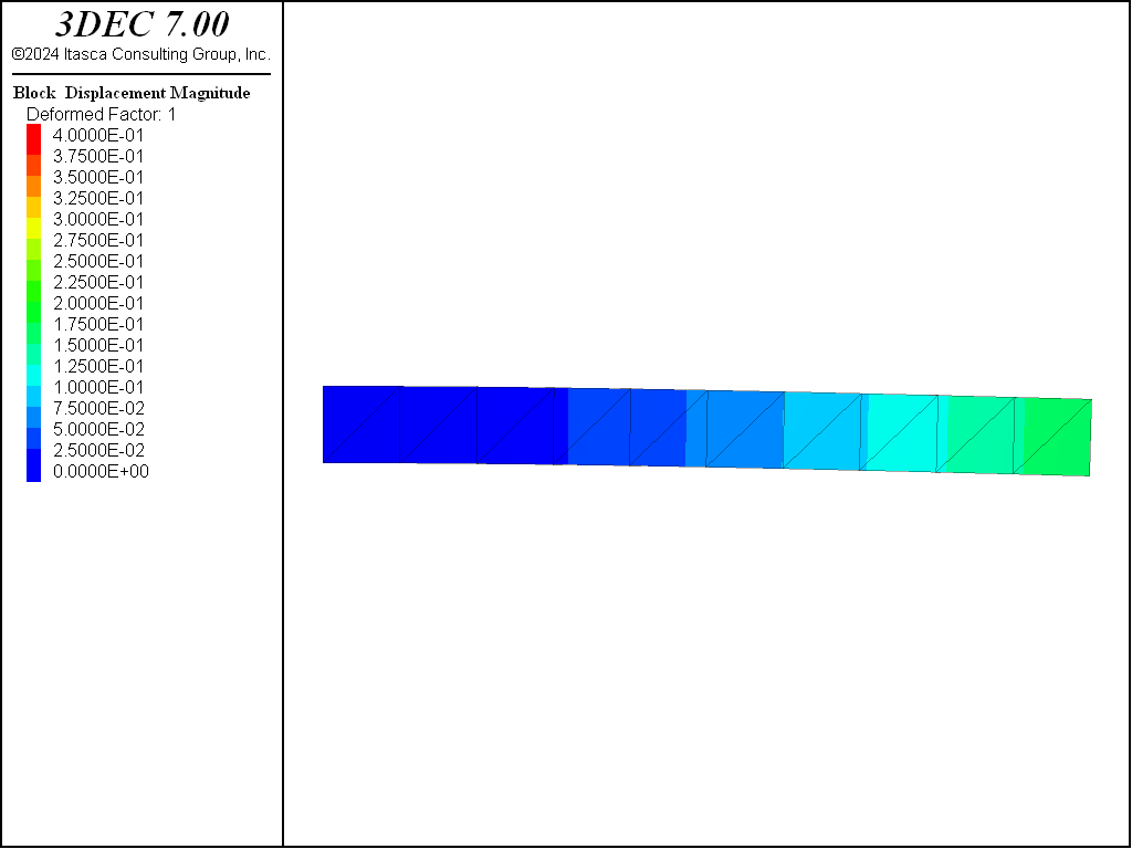
If the beam is modeled with 10 hexahedral zones along its length, the resulting displacement is shown in Figure 3. The error in this case is more than 50%.
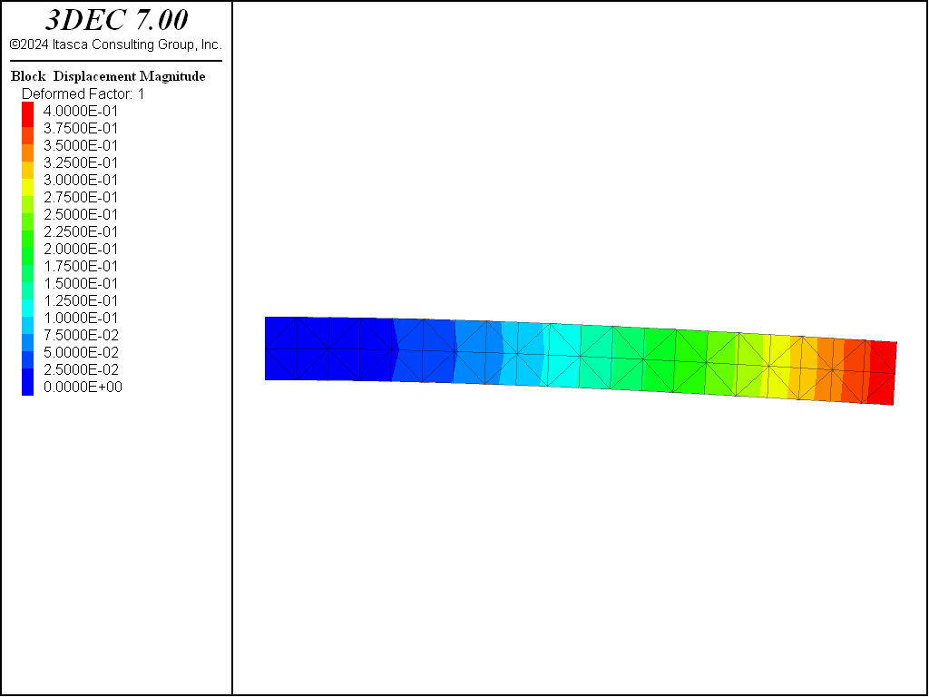
If the same beam is modeled with 10 finite elements, the result is shown in Figure Figure #fbeam-fem. In this case the error is less than 1%.
fem_beam.dat
model new
model config feblock

[a = 1.0]
[force = 100.0]
[E = 1e6]
[L = 10.0]

block create brick 0 [L] 0 [a] 0 [a]

feblock generate 1 1 1

block zone cmodel assign el
block zone prop dens 2000 young [E] poiss 0.2

block gridpoint apply vel 0 0 0 range pos-x 0

; divide force by 3 since it is being applied to 3 gridpoints
block gridpoint apply force-z [-1.0*force/3.0] range pos-x [L] pos-z [a]

model large-strain off
model solve

fish def solution
  local moi = a*a/12.0
  deflection_analytical = force*L*L*L/(3*E*moi)
  local gp = block.gp.near(10,1,1)
  deflection_3dec = -1.0*block.gp.disp.z(gp)
  error_ = 100.0*math.abs(deflection_3dec - deflection_analytical)/deflection_analytical
  io.out("Error: "+string(error_)+"%")
end
[solution]

model save 'beam-fem'

; test FISH
fish def plot_gausspoints
  ; loop through finite elements
  loop foreach local felem feblock.list
    ; loop through gauss points
    loop local i (1,feblock.gauss.num(felem))

      ; make scalar for plotting
      local pos = feblock.gauss.pos(felem,i)
      local uds = data.scalar.create(pos)
      data.scalar.extra(uds,1) = i

      ; make tesnor for plotting stress
      local udt = data.tensor.create(pos)
      data.tensor.value(udt) = feblock.gauss.stress(felem,i)
    end_loop
  end_loop
end
[plot_gausspoints]
Example: Tunnel Liner
As shown above, 20-noded finite elements are much better at simulating bending than regular hexahedral finite volume zones. One application therefore is to use them to model tunnel liners.
The simple tunnel example from the User’s Guide is reconstructed and finite elements are used to simulate the liner. The construction of the tunnel and the bringing to initial equilibrium are exactly the same as in the User’s Guide except that model config feblock must be given before blocks are created.
The tunnel is then excavated and reaction forces are reduced to 50% as in the User’s Guide example. Now, blocks are created around the surface of the tunnel representing a liner with a thickness of 0.2 m as shown in the data file below. After the blocks are created, they are turned into finite elements with the command feblock generate.
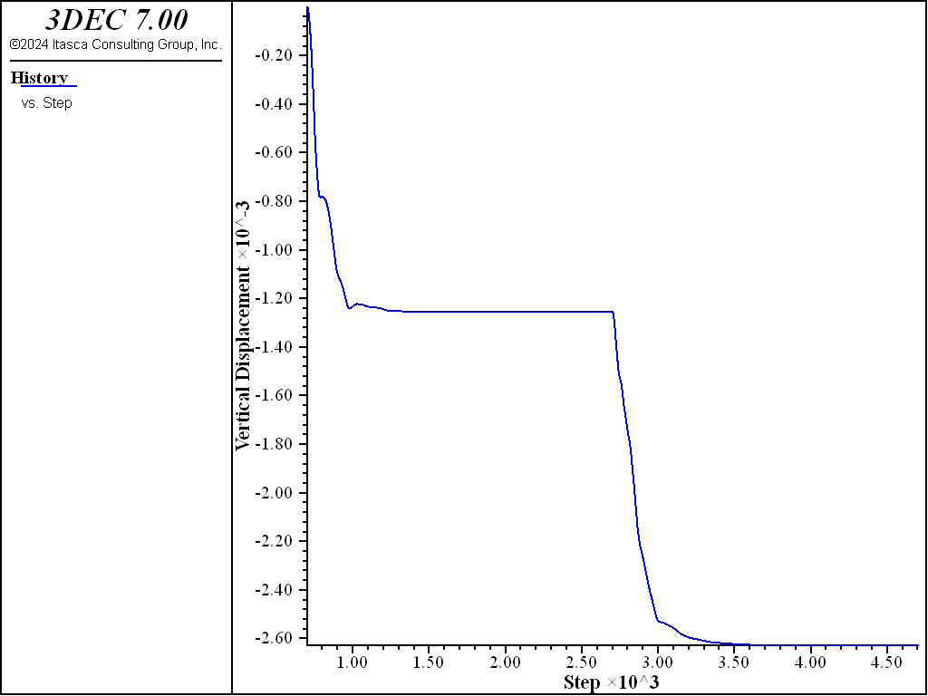
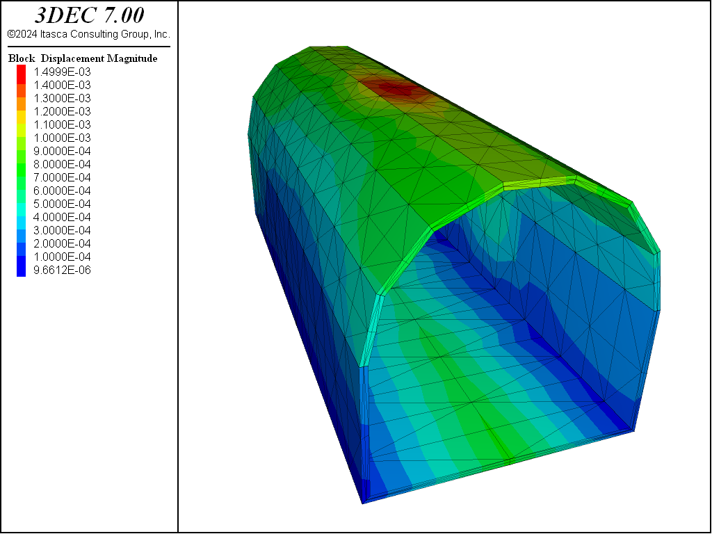
Properties are assigned to the liner elements and the contacts between the liner and the rock. The model is then cycled until displacements are not changing (Figure 5). The displacements in the liner are shown in Figure 6.
tunnel_linerblocks-fem.dat
model rest 'tunnel_ini'

block gridpoint ini disp 0 0 0
model mech time-total 0

; mark boundary faces
block face group 'surface' range group-int 'rock' 'exc'

; delete interior blocks
block delete range group 'exc'

; apply 50% stress
block face apply stress -1.35 -1.35 -2.7 0 0 0 range group 'surface'

; reapply front and back fixities
block gridpoint apply vel-y 0 range pos-y -10.0
block gridpoint apply vel-y 0 range pos-y  10.0

; history of point in wedge
history delete
block hist name 'Vertical Displacement' dis-z pos 0 -0.2 4.3
model cyc 2000

; remove loads
block face apply-remove stress range group 'surface'

; make prisms to define liner blocks
fish define make_liner

  thick = 0.2

  ; bottom left
  p1 = vector(-4,-10,-4)
  p2 = vector(-4+thick,-10,-4+thick)
  p3 = vector(-4+thick,-10,0)
  p4 = vector(-4,-10,0)

  p1b = p1 + vector(0,20,0)
  p2b = p2 + vector(0,20,0)
  p3b = p3 + vector(0,20,0)
  p4b = p4 + vector(0,20,0)

  command
    block create prism face-1 [p1] [p2] [p3] [p4] &
           face-2 [p1b] [p2b] [p3b] [p4b] &
           group 'liner'
  end_command

  ; bottom
  p4 = p2
  p4b = p2b

  p2 = vector(4,-10,-4)
  p3 = vector(4-thick,-10,-4+thick)
  p2b = p2 + vector(0,20,0)
  p3b = p3 + vector(0,20,0)

  command
    block create prism face-1 [p1] [p2] [p3] [p4] &
           face-2 [p1b] [p2b] [p3b] [p4b] &
           group 'liner'
  end_command

  ; bottom right
  p1 = p2
  p4 = p3
  p1b = p2b
  p4b = p3b

  p2 = vector(4,-10,0)
  p3 = vector(4-thick,-10,0)
  p2b = p2 + vector(0,20,0)
  p3b = p3 + vector(0,20,0)

  command
    block create prism face-1 [p1] [p2] [p3] [p4] &
           face-2 [p1b] [p2b] [p3b] [p4b] &
           group 'liner'
  end_command
;
  ; center and radius of circular arc
  local txc =  0.0
  local tzc =  0.0
  local tr  =  4.0

  ; 8 segments
  local seg = 8
  loop i (1,seg-1)
    local theta = 180.0/(seg-1)*(i-1)*math.degrad
    local px1 = txc + tr*math.cos(theta)
    local pz1 = tzc + tr*math.sin(theta)
    local theta2 = 180.0/(seg-1)*(i)*math.degrad
    local px2 = txc + tr*math.cos(theta2)
    local pz2 = tzc + tr*math.sin(theta2)
    local px3 = txc + (tr-thick)*math.cos(theta2)
    local pz3 = tzc + (tr-thick)*math.sin(theta2)
    local px4 = txc + (tr-thick)*math.cos(theta)
    local pz4 = tzc + (tr-thick)*math.sin(theta)
    command
      block create prism face-1 [px1] -10 [pz1]  [px2] -10 [pz2]  [px3] -10 [pz3]  [px4] -10 [pz4] ...
        face-2 [px1] 10 [pz1]  [px2] 10 [pz2]  [px3] 10 [pz3]  [px4] 10 [pz4] ...
        group 'liner'
    end_command
  end_loop
end

[make_liner]

;
block hide range group 'liner' not

; generate finite elemnts
;specify large size in x and z direction so liner is only 1 element thick
feblock generate 20 2.5 20
;
; properties for concrete liner
block zone cmodel assign elastic
block zone prop density 0.0024 young 30000 poiss 0.2

; concrete rock interface
block hide off

block contact gen-sub

block contact jmodel assign mohr range group-intersect 'liner' 'rock'
block contact prop stiffness-normal 10000 stiffness-shear 2000 friction 35 range group-intersect 'liner' 'rock'

; apply front and back fixities for liner
block gridpoint apply vel-y 0 range pos-y -10.0
block gridpoint apply vel-y 0 range pos-y  10.0
;
; ---------------------------------------------------------------------
;
;
; cycle 1 to force calculation of contact normals
model cyc 1
model cycle 2000
;
model save 'tunnel_linerblocks_fem'
Example of Creating a Finite Element Base Model of a Dam in 3DEC
This example can be found at Finite Element Dam
References
Brierley, G. “The Performance during Construction of the Liner of a Large, Shallow Underground Opening in Rock.” Ph.D. Thesis, University of Illinois at Urbana-Champaign (1975).
Cheung, Y. K., I. P. King and O. C. Zienkiewicz. “Slab Bridges with Arbitrary Shape and Support Conditions – A General Method of Analysis Based on Finite Elements,” Proc. Inst. Civ. Eng., 40, 9-36 (1968).
Desai, C. S., and J. F. Abel. Introduction to the Finite Element Method – A Numerical Method for Engineering Analysis. New York: Van Nostrand Reinhold Company (1972).
Dixon, J. D. “Analysis of Tunnel Support Structure with Consideration of Support-Rock Interaction,” U.S. Dept. of Interior, Bureau of Mines Investigation, Report RI7526 (June 1971).
Hughes, T. J. R. The Finite Element Method: Linear Static and DynamicFinite Element Analysis. Prentice Hall (1987).
Lemos, J. V. “Modelling of Arch Dams on Jointed Rock Foundations,” in Prediction and Performance in Rock Mechanics & Rock Engineering (Proceedings of ISRM International Symposium EUROCK ‘96, Turin, Italy, September 1996), Vol. 1, pp. 519-526. G. Barla, ed. Rotterdam: A. A. Balkema (1996).
Lemos, J. V., et al. “Experimental Study of an Arch Dam on a Jointed Foundation,” in Proceedings of the Eighth International Congress on Rock Mechanics (Tokyo, Japan, September 1995), Vol. 3, pp. 1263-1266. T. Fujii, ed. Rotterdam: A. A. Balkema (1995).
Lorig, L. J. “A Hybrid Computational Model for Excavation and Support Design in Jointed Media.” Ph.D. Thesis, University of Minnesota (1984).
Monsees, J. E. “Station Design for the Washington Metro System,” in Proceedings of the Engineering Foundation Conference – Shotcrete Support. ACI Publication SP-54 (1977).
Paul, S. L., et al. “Design Recommendations for Concrete Tunnel Linings,” University of Illinois, DOT Report No. DOT-TSC-UMTA-83-16 (1983).
Zienkiewicz, O. C. The Finite Element Method. London: McGraw-Hill Book Company (UK) Limited (1977).
| Was this helpful? ... | 3DEC © 2019, Itasca | Updated: Feb 25, 2024 |

