Generating Block Assemblies
The preceding section, i Creating Single Blocks, describes the creation of single blocks of different shapes using the block create command. It is also possible to create assemblies of blocks to fit a volume using the block generate command. Different methods for using block generate are described in the following sub-sections. Importing and exporting block assemblies from third-party programs (e.g., Griddle) is also described here.
Generating Blocks from Geometry
Cutting out complicated shapes using the block cut geometry command can produce many tiny blocks with bad geometries, which adversely affects model run times and numerical stability. Another option is to fill a closed volume with tetrahedral blocks that match the volume boundary. This can be done with the block generate from-geometry command.
The user must first create or import a surface geometry (see i Geometry). The surface geometry must be a clean, closed volume without holes. The volume is then filled with tetrahedral blocks of desired size. A gradation may be specified to gradually enlarge blocks moving away from the surface: smaller blocks will be created at highly detailed surfaces, larger blocks will be generated where the surface mesh is less detailed.
A simple example is shown below. A DXF that defines a tunnel within a box is imported (Figure 1). Blocks are then generated to fill the volume. A minimum edge length of 2 and a maximum edge length of 5 are specified. A gradation of 1.5 is also assigned: the block edge length will increase at a rate of 1.5 when moving away from the (detailed) surface.
The resulting blocks are shown in Figure 2. Note that the blocks are not automatically joined. It is advisable to add a block join command after generation.
model new
geometry import 'tun.dxf'
block generate from-geometry set 'tun' ...
  minimum-edge 2 maximum-edge 5.0 gradation-volume 1.5
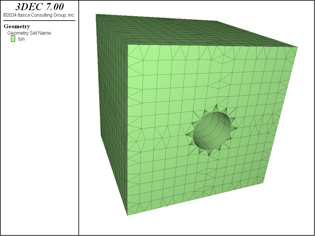
Figure 1: Geometry surface used to create the tunnel model.
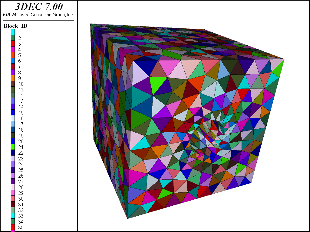
Figure 2: Blocks making up the tunnel model.
Creating a large assembly of tetrahedral blocks and joining them can be inefficient. Even though the contact calculations are skipped at the joined contacts, 3DEC still looks through all of the contacts to check if they are joined. Data structures are also set up for all of the contacts, faces, and duplicated gridpoints, causing the model to use more memory.
Instead of joining, it is possible to “merge” the blocks to become zones within a single block. This is much more efficient than creating the blocks, joining them, and then zoning them. Adding the merge keyword to the block generate from-geometry command causes the merge operation to occur. If the imported geometry consists of multiple closed volumes, then the blocks will not be merged across the surface boundaries. This technique creates models where different blocks define different layers or excavation stages.
The geometry of Figure 1 is actually four separate surfaces dividing the tunnel into four quadrants. When the merge keyword is added to the block generate from-geometry command in the above example, Figure 3 results. 3DEC creates four separate blocks that are already zoned.
The drawback to this approach is that once blocks are zoned, they cannot be cut.
See i Importing and Merging for more details on the merge logic in 3DEC.
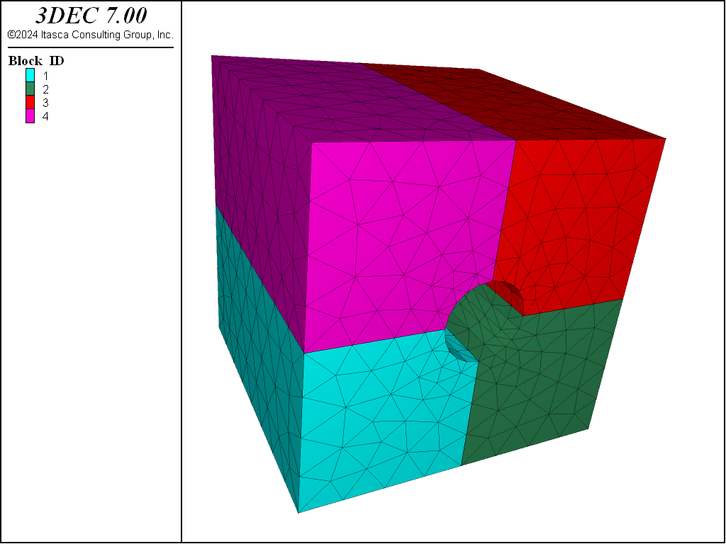
Figure 3: Blocks making up the tunnel model when the merge keyword is used.
Generating Blocks from VRML
In CAD programs such as Rhino (Robert McNeel and Associates, 2020), solids may be exported as VRML 2.0 files. The individuality of each solid is preserved as a separate VRML “Shape” construct. In other words, a collection of convex solids in Rhino that are exported to a VRML 2.0 file may be translated into 3DEC rigid blocks using the block generate from-vrml command.
Creating VRML solids
Solids created for export to 3DEC must be convex and closed. Below are some tips for generating valid solids in Rhino.
- Splitting a solid in Rhino does not result in two solids. The
Edit|SplitorEdit|Trimcommands operate on the surface of the solid and, as such, result in unclosed surfaces. If usingSplitorTrim, also useSolid|Cap Planar Holesor some other device to close them. - Instead of
SplitorTrim, useSolid|Solid edit tools|Wire cut, which always results in two solids. - Boolean operations among solids always result in solids.
- If the desired solid output is “almost” convex, when exporting it as a VRML 2.0 file it is preferable to use the
Detailed Controls(instead of theSimple Controls) menu. Uncheck everything except “Simple plane” and set everything to zero, except for the “Minimum edge length,” which should be set to a large value. This will ensure that curved regions of the solid will be flat in the VRML output file (Figure 4).
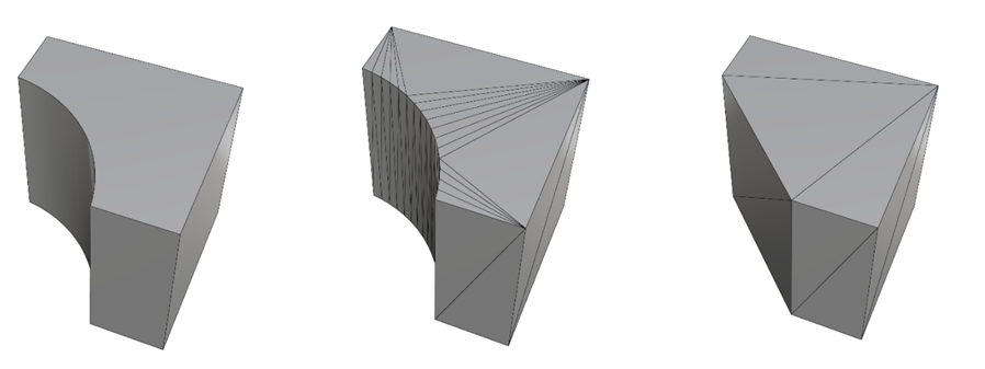
Figure 4: Left: This solid is not convex. Middle: During the VRML export process, the solid is facetized, but the curve is discretized with multiple segments and the result is not convex. Right: The facetization is as coarse as possible, (large Minimum edge length) resulting in a convex VRML representation.
Example: Borehole in a Block
This example provides step-by-step instructions for building a borehole from a collection of convex shapes in Rhino. The shapes are then saved in VRML formal and imported into 3DEC. The Rhino file, 3DEC project, and 3DEC data file can be found in .
- Start Rhino and select to corner, height. Rhino asks for the location of the first corner of the base.
- Enter (with no blanks in between values) -4,-4,-4 then press :kdb:`Enter`. Rhino asks for the location of the other corner of the base.
- Enter 4,4,4. Rhino asks for the height. Press :kdb:`Enter` to set the height equal to the width of the box. An 8 x 8 x 8 box is created.
- In the Top view, Select , radius. Enter (0,0,0) to place the center of the circle and enter 1, followed by :kdb:`Enter` to complete a circle of radius 1 centered on the origin.
- Select the circle and enter
WireCutin the command line. - Click on the Cube and press :kdb:`Enter` three times to split the cube into two solids. Notice that the circle is still highlighted. Press :kdb:`Enter` to delete it.
- In the Top view select . Enter -8,0,0 for the Start of the line, followed by :kdb:`Enter`.
- Enter 8,0,0 for the End of line, followed by :kdb:`Enter`, to complete the line.
- Click on the label of the Top view to activate it. Select the line, and select (not Rotate 3D). Rhino responds with center of rotation (Copy).
- Ensure that Copy=Yes. If not, click on the word Copy to tell Rhino to rotate a Copy of the line. Rhino asks for the center of rotation.
- Enter 0,0 for the coordinates in the Top view. Rhino asks for the Angle of rotation.
- Enter 22.5 to complete the rotation. Press :kdb:`Enter` twice.
- Select both segments (holding down the
Shiftbutton) and select . Rhino responds with center of rotation (Copy). Ensure that Copy=Yes. - Enter 0,0 for the center of rotation.
- Enter 45 degrees for the angle of rotation. Press :kdb:`Enter` twice. There should now be four lines.
- Select all four segments, use Copy, Paste and a Rotation of 90° to get a total of eight line segments fanning out of the origin in the Top view (Figure 5).
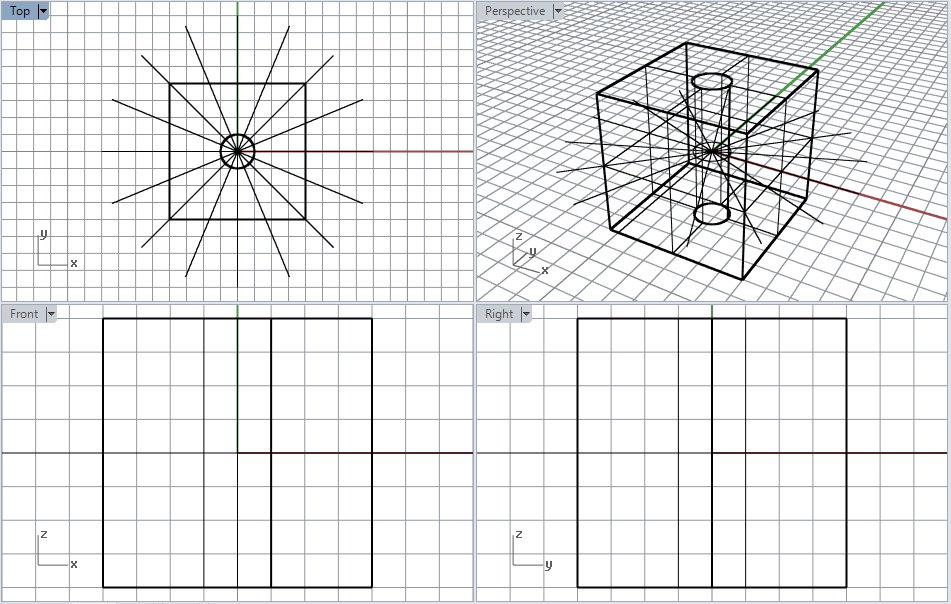
Figure 5: The cored block and eight line segments used to cut the block into equal pieces.
- In the Top view, select the horizontal line segments (the first one created). Select . Rhino asks for a Surface.
- While still in the Top view, select the cube. Enter <ENTER>. Rhino now asks for the First cut depth point. Ensure that KeepAll=Yes (if not, click it to change from No to Yes). Press :kdb:`Enter`.
- In the Top view, select another line segment (inclined at 22°), select and select the top half of the box, then press :kdb:`Enter` twice.
- While the same line segment is selected, select again, this time selecting the lower half of the box, then press :kdb:`Enter` twice to cut the lower half in two, as well (Figure 6).
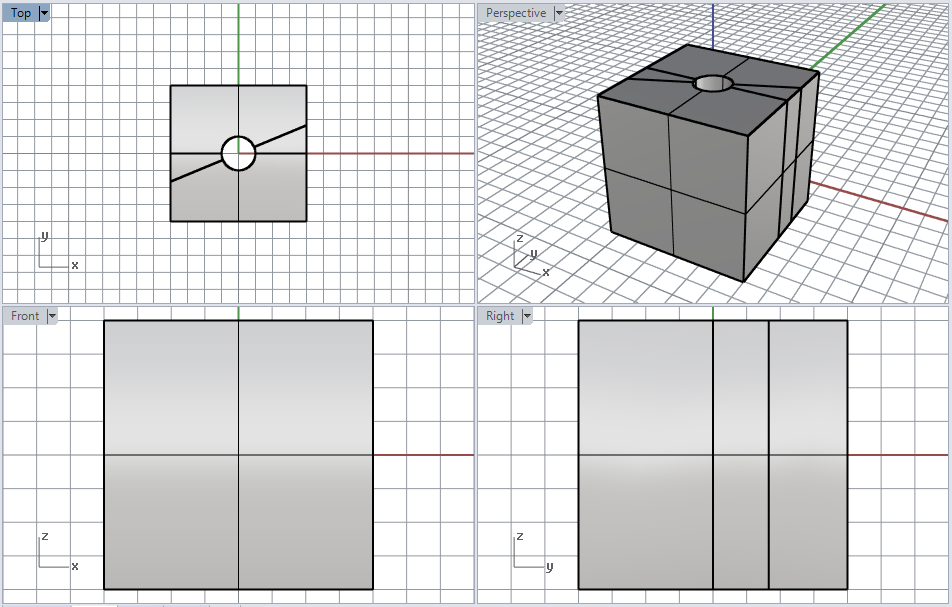
Figure 6: The model after cutting with the second line.
- Use repeatedly with the remaining lines and solids and continue splitting until there are 16 pieces (Figure 7).
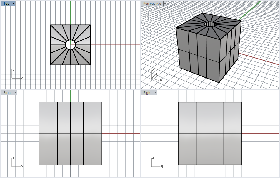
Figure 7: The cored block has been cut into 16 equal sections using Wire Cut.
- Select the 16 solids and use to export the solids as a VRML 2.0 file. In the VRML Export options window, select “version 2.0”. When the Polygon mesh detailed options dialog box opens, uncheck everything except “Simple planes”, set all values to 0 except for the Minimum edge length, which should be set to a large number, such as 1000, and click
OK. Save the file with the name “hole”. This will create a file called “hole.wrl” in the working folder.
- Start 3DEC, run a
block generate from-vrmlcommand with the file “hole.wrl” as shown below. Finally plot the blocks to see the model (Figure 8).
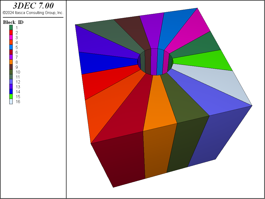
Figure 8: 3DEC model of the hole in a block.
See Flying Buttress and Flemish Wall for other examples of using VRML files in 3DEC.
Surface Topography and Face Extrusion
3DEC provides a block generate from-topography command to generate a grid between the surface faces of an existing grid and a geometry set that characterizes the topography. The blocks are created by extruding from faces in a specified range along a ray direction to a specified geometry set. This can be used to create a series of irregular non-intersecting layers, or most commonly, to add a layer of blocks to the top that conforms to an irregular topographic surface. Some simple examples follow.
To create a grid that conforms to a topographic surface, a geometry set must be specified. The easiest way to create a geometry set is via the geometry import command. Additional commands are available for manipulation of edges, polygons, and nodes, as well as other operations on geometric sets in their entireties.
An initial grid must exist before using the block generate from-topography command. Only the block faces satisfying all of the following criteria will be selected:
- The faces must be in the range.
- The faces must be on the existing grid surface, and any interior faces will be neglected.
- The outward normal vector of the faces must make an angle with the ray of less than 89.427 degrees. This will exclude the faces parallel to the ray (with a crossing angle of 90 degrees) or the faces facing a relatively opposite direction of the ray (with a crossing angle greater than 90 but not greater than 180 degrees).
The data file in the following example first imports geometry data from the STL format file ‘surface1.stl’ and places it into a geometry set called ‘surface1’. (By default, the geometry set name is the same as the file name just imported.) The data file then creates a background grid with a group name ‘Layer1’. It can be seen that if projected to the \(x-y\) plane, the geometry set will fully cover the background grid, so any node in a valid face in the range will have an intersection point with the geometry set if extruding along the ray direction.
Next the block generate from-topography command is added. In the command, the ‘surface1’ geometry set is specified. No ray direction is specified, so the default direction (0, 0, 1) is used by default. The segment number is 8, so eight blocks will be created between the selected faces and the geometric surface. The ratio, which is set to 0.8, changes the distribution of zone sizes as zones approach the surface. In this case each zone is 0.8 times the size of the next. The newly created zones will be assigned the group name ‘Layer2’ in slot ‘Default’. A range of the faces on the top surface of the existing grid (group Layer1) are subjected to extrusion to the geometry set. The completed grid is shown in Figure 9. The topography of the geometry set is correctly featured in the grid.
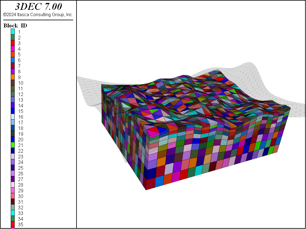
Figure 9: 3DEC model of blocks extruded to match imported surface geometry.
model new

block create brick 0 15000 0 12000 -4000 -3000 group 'Layer1'
block densify segment 20 20 1

geometry import 'surface1.stl'

block generate from-topography geometry-set	'surface1' ...
  direction 0 0 1 segments 8 ratio 0.8 group "Layer2" range p-z -3000
Voronoi Block Generation
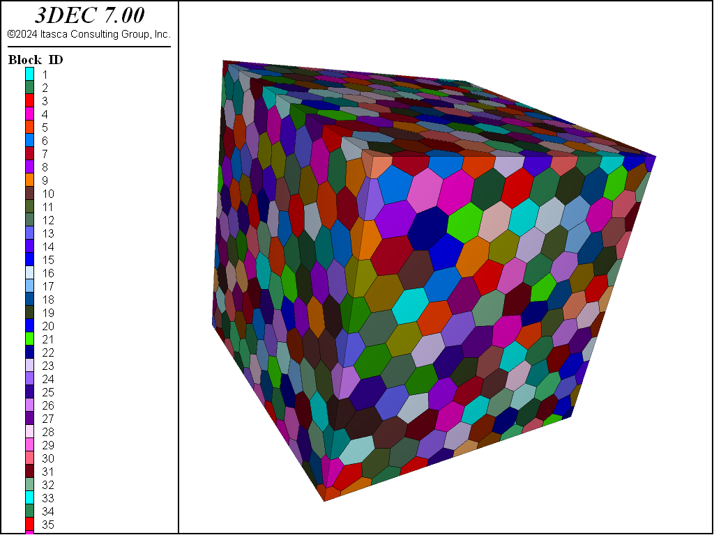
The command block generate voronoi can be used to create random Voronoi blocks to fill a closed volume defined by a geometric set (closed surface). This Voronoi blocking is useful to simulate crack propagation. “Fracturing” occurs when the joint strength between Voronoi blocks is exceeded.
The Voronoi algorithm begins by distributing points randomly on and within the geometric set. The distance between two seeds can be controlled by the keyword maximum-edge and minimum-edge. Next, the Delaunay triangulation is created between all seeds. Finally, the Voronoi blocks are created by constructing perpendicular bisectors of all segments of the Delaunay triangulation. The blocks are truncated at the boundaries of the tessellation region by the geometric set.
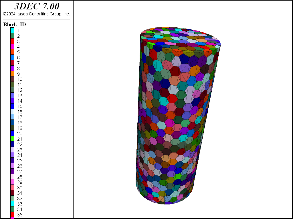
Note that Voronoi tessellation only works for a single, closed, convex volume. Note also it is generally necessary to set the block tolerance by hand when using block generate voronoi command. This is because the default tolerance is calculated based on the size of the first created block, assuming that this block will be cut up to create the model. When the model is created by putting together multiple blocks, the default is not appropriate. As a rule of thumb, set the block tolerance to 1% of the block size.
Examples for generating Voronoi block assemblies for a simple cube and cylinder are shown below. These examples can be found in .
model new
block tolerance 0.01
geometry import 'cube.dxf'
block generate voronoi set 'cube'  min-edge 0.5  max-edge 1.0
model new
block tol 6e-5
geometry import 'cylinder.dxf'
block generate voronoi set 'cylinder'  max-edge 0.006
Block Import/Export
In addition to the built-in methods of mesh generation, meshing created by third-party applications outside 3DEC can be imported. Griddle 1.0 produces a file with a series of 3DEC 5.2 commands used to create rigid blocks. These commands can be converted with the built-in conversion tool to create 3DEC 7.0 models. Griddle 2.0 and above exports a 3DEC grid file that is a much more compact, understandable representation of blocks. The 3DEC grid file can also be binary, which makes it even smaller and faster to import.
The 3DEC grid file can define either rigid or deformable (zoned) blocks. Note, however, that importing a zoned block using a grid file will result in a larger and slower model than the equivalent model zoned in 3DEC. The zoned grid file option is therefore most useful if zoned concave blocks are desired (3DEC can only mesh convex blocks), or if advanced zoning features are required that are not available within 3DEC. See i Importing and Merging for more details on importing zoned blocks in 3DEC.
The grid files can be imported into a 3DEC model by using the block import command, by using the entry in the main menu. The file format for 3dgrid files is described in the block import documentation.
Once imported, the file should appear as an entry in the “Data Files” section of the i Project pane and will be added to any bundle made to archive or communicate the project.
Blocks and zones can also be exported from 3DEC (block export).
References
Robert McNeel & Associates. Rhinoceros Version 6.0, https://www.rhino3d.com/ (2020).
| Was this helpful? ... | 3DEC © 2019, Itasca | Updated: Feb 25, 2024 |