Zone Types
If a deformable block analysis is required, models with different densities of block zoning should be evaluated once the block cutting and boundary location have been established. The block zone generate command or block zone generate-new command is used to specify the zoning density and zone type.
The highest density of zoning should be in regions of high stress or strain gradients (e.g., in the vicinity of excavations). It is not advisable to have large jumps in zone size between adjacent blocks. For reasonable accuracy, the ratio between zone volumes in adjacent polyhedra should not exceed roughly 4:1.
Tetrahedra
The block zone generate edgelength command or the block zone generate-new command will automatically create tetrahedral zones within an arbitrarily shaped convex polyhedron. If block-cutting results in blocks that are long and thin, it is recommended that these blocks be further cut and joined before generating zones. By doing this, zones with an aspect ratio closer to unity can be generated. i Block Metrics describes methods that can be used to evaluate the quality of blocks before zoning.
In general, plasticity results from tetrahedral zones are not as accurate as those from hexahedral or higher order zones (see below). 3DEC assumes that the important mechanisms that lead to large displacements are related to movement on joints and faults. If very accurate plasticity calculations are required, it is recommended that hexahedra be used. If this is not possible, due to the geometry of the problem, then it is highly recommended that nodal mixed discretization is turned on using the block zone nodal-mixed-discretization. The nodal mixed discretization scheme produces more accurate plasticity results in most cases. Details on this formulation can be found in i Deformable Block Motion.
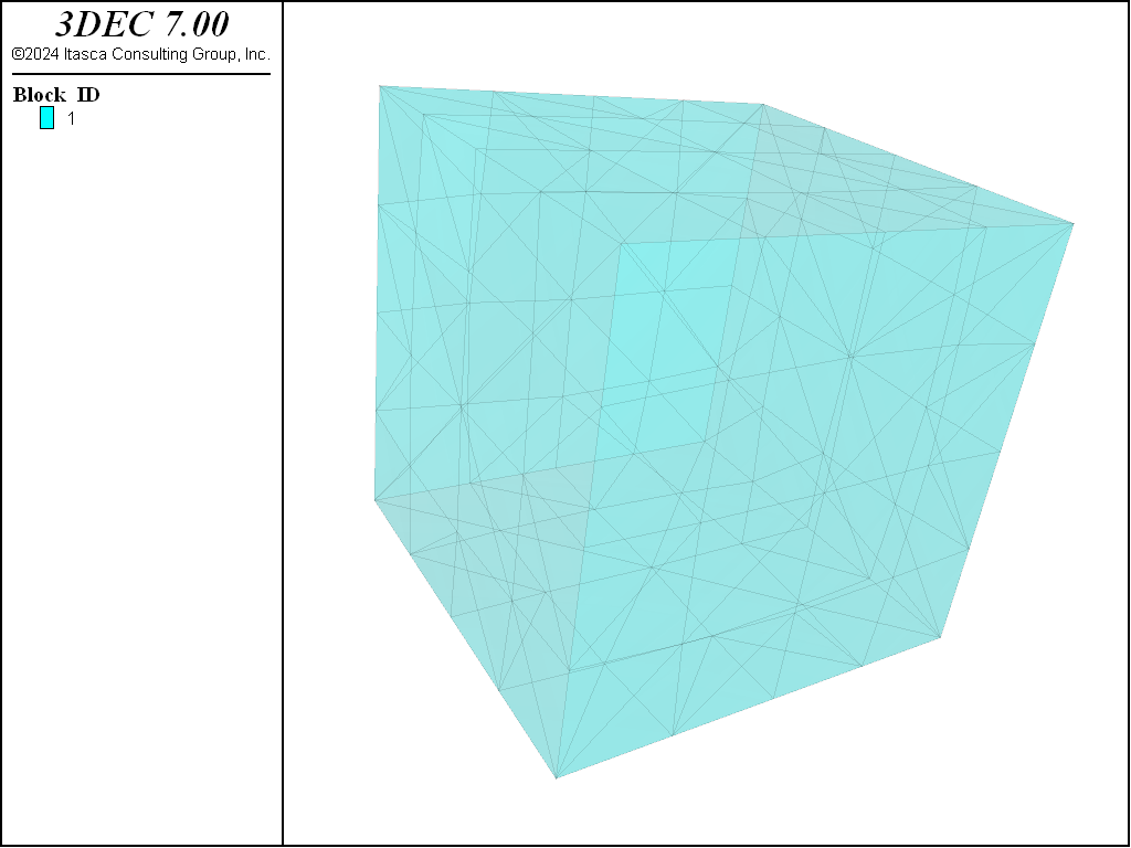
A single 2×2×2 cubic block zoned with tetrahedra using the following command is shown in Figure 1.
block zone generate edgelength 0.5
Hexahedra
The block zone generate hexahedra command only generates zones within six-sided polyhedra. This command creates mixed-discretization (m-d) zones (two overlays of five tetrahedral zones) that provide better accuracy for problems involving failure and collapse of the intact blocks. (See i Deformable Block Motion in the Theory and Background section for details.) Hexahedral zones will provide more accurate results in problems involving plastic failure of the intact material. However, because these can only be used in 6-sided blocks, their applicability in “real-world” problems is limited.
Tetrahedral zones can provide reasonable accuracy for certain failure modes (e.g., confined compression loading). However, this type of zoning does not produce an accurate prediction for collapse loads in bearing capacity problems. Comparisons of results using block zone generate hexahedra versus block zone generate edgelength for plasticity analysis are given in the following verification problems: i Rough Square Footing on a Cohesive Frictionless Material and i Cylindrical Hole in an Infinite Mohr-Coulomb Medium.
Note that hexahedral zones cannot be used with joint fluid flow.
Be aware that 3DEC actually generates ten overlapping tetrahedra for each hexahedral zone. The underlying calculations are performed by mixing the tetrahedra as described in i Deformable Block Motion, but when plotting zones, you will see the tetrahedra, each with its own stress and strain. Similarly, when you give the command block zone list, information about the tetrahedral zones will be listed, rather than the hexahedra.
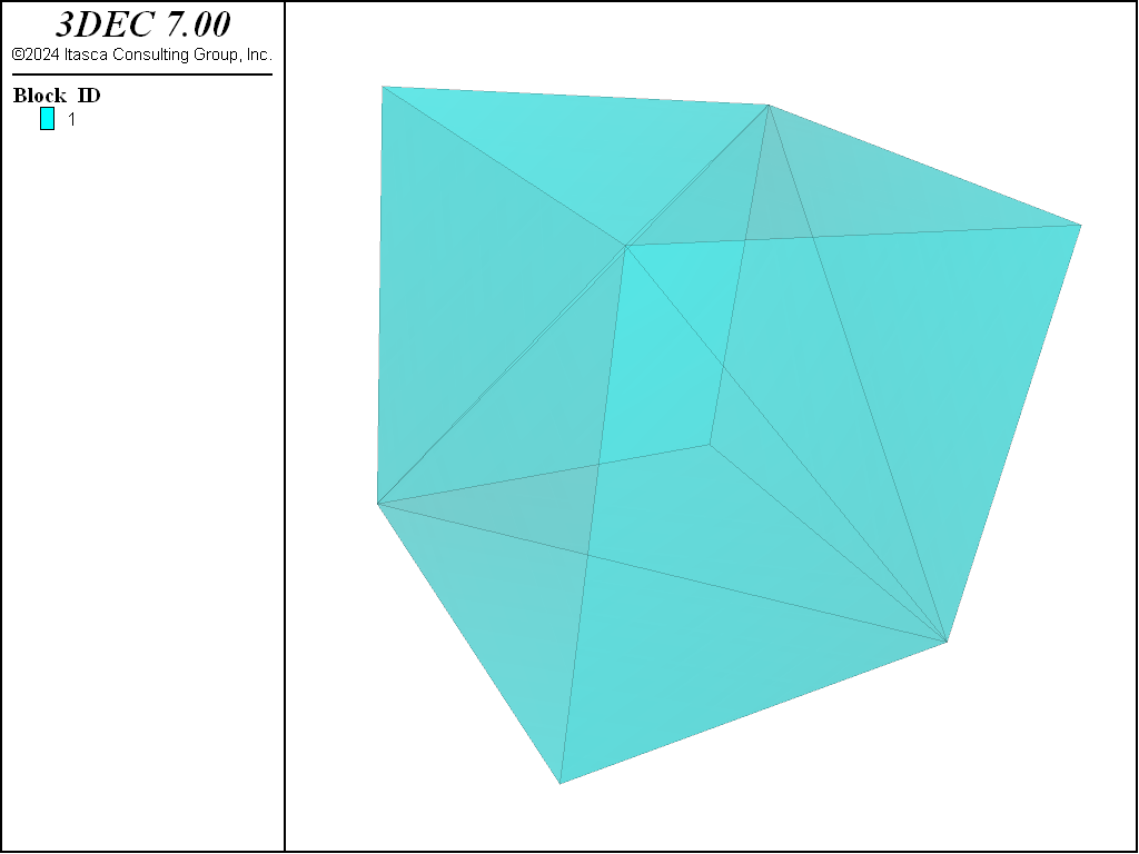
The same block as above is zoned with the following command to create a single hexahedral zone. The resulting block plot is shown in Figure 2.
block zone generate hexahedra divisions 1 1 1
Higher-Order Tetrahedra
The block zone generate higher-order-tetra command produces high-order tetrahedral zones that can be used in blocks that cannot be zoned with m-d (hex) zoning. These zones have additional gridpoint nodes and are more accurate than the standard tetrahedral zoning. An extra gridpoint is added to the center of each zone edge. The command may be used only after the blocks have been zoned using the normal block zone generate commands. The model configure hotetra command must be given before any blocks are created.
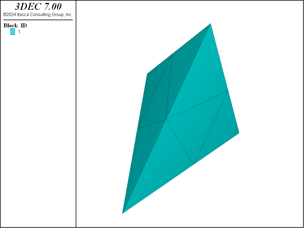
The plasticity solution for the high-order zones is more accurate than for the normal constant-strain tetrahedral zones. However, there are some drawbacks. The high-order elements are incompatible with the free-field boundary and with joint fluid flow. In addition, the high-order zones are stored and plotted as an assembly of eight tetrahedra. The following commands will create a single tetrahedral block with a single higher-order tetrahedral zone in it. Figure 3 shows how the zone is actually plotted as eight smaller tets.
model config hotetra
block create tet 0,0,0 1,0,0 0.7,0.7,0 0.5,0.35,0.7
block zone generate edgelength 1
block zone generate high-order-tetra
By default, a separate stress value is plotted in each sub-tet. However, stresses in the high-order zones are projected to the gridpoints to give accurate stress results (see block gridpoint list stress). The projected stresses can also be plotted by choosing Stress from the contour-by menu of the block plot item.
It is tempting to use the high order tetrahedra (rather than regular tetrahedra) so that a more accurate plasticity solution can be obtained in deformable blocks. However, the accuracy of the contact force calculations is actually diminished due to the presence of the midside nodes. The error increases as the stiffness of the joints increase (relative to the zone stiffness).
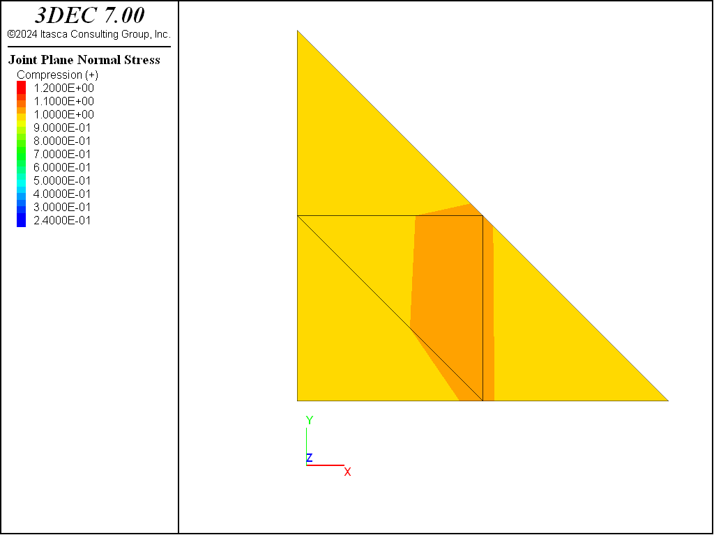
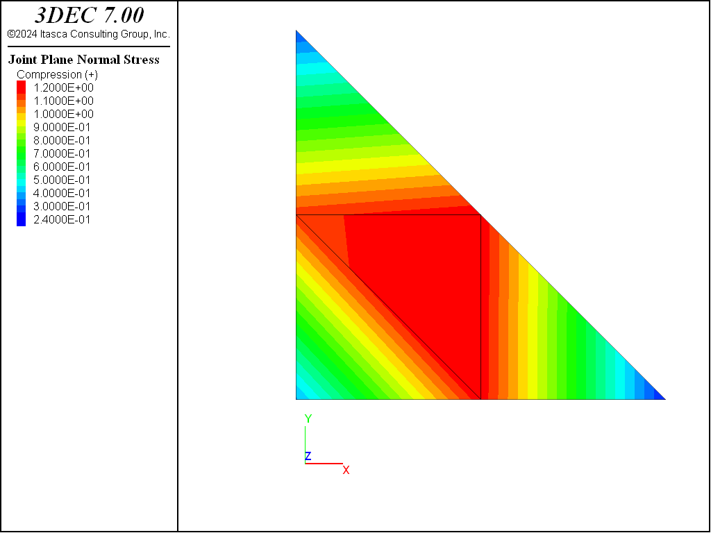
Figure 4 shows a simple block model for testing the joint behavior. This model results in a joint made up of a single triangular zone face, with sixgridpoints. The zones are assigned a Young’s modulus of 50 GPa. The model is then loaded to produce a stress of 1 MPa in the zones and on the joint.
For a joint stiffness of 1 GPa/m, the results are good and the joint stress is close to 1 MPa (Figure 5). When the joint stiffness is increased, it is clear that the midside nodes exhibit forces that are too high, while the corner nodes shows forces that are too low (Figure 6). The data file for this test is shown below. For a model with stiff joints, using regular tetrahedra with block zone nodal-mixed-discretization on is recommended.
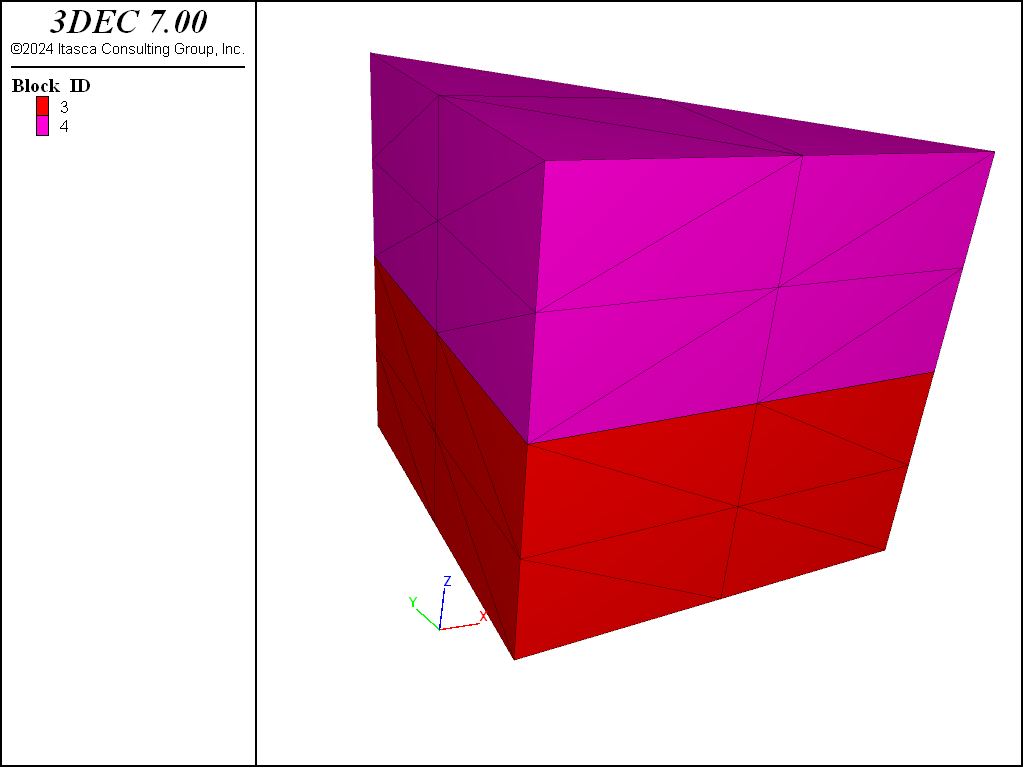
Figure 4: Model used to test accuracy of joint force calculations with higher-order tetrahedral zones.
program log on
program log-file 'hotet-jkn-1.log'
;
model new
;
model configure highorder
;
block tolerance 0.001
;
block create brick -1 1
block cut joint-set
block cut joint-set dip 90 dip-direction 45 origin 0 0 0
block delete range position-x 0 1
;
block zone generate edgelength 5
block zone generate high-order-tetra
;
block zone cmodel assign elastic
block zone property density 0.0025 young 50000 poiss 0.25
block contact property stiffness-normal 1000 stiffness-shear 100000 friction 40
block insitu stress 0 0 0 0 0 0
block contact property stiffness-normal 1000 stiffness-shear 100000 friction 40

block gridpoint apply velocity-z 0 range position-z -1
block gridpoint apply velocity-x 0 range position-x -1
block gridpoint apply velocity-y 0 range position-y -1
;
block gridpoint apply velocity-z -1e-3 range position-z 1
;
block history displacement-x position 1 1 1
block history displacement-y position 1 1 1
block history displacement-z position 1 1 1

model save 'hotetra-joints1'
;
; zdisp (top) = 1.04e-3, for szz=1
model mechanical timestep fix 2e-5
model large-strain off
model cycle 52000
;
block gridpoint apply velocity-z 0.0 range position-z 1
model cycle 500

block contact list force
;
model save 'hotet-jkn1'

program log off
;
;
;
;
| Was this helpful? ... | 3DEC © 2019, Itasca | Updated: Feb 25, 2024 |

