structure beam cmodel command
Syntax
- structure beam cmodel keyword
Primary keywords:
Assign or get information about beam constitutive models. This command allows one to assign a constitutive model to a specified beam-type element, query properties and states of constitutive models, and assign and query the integration scheme for plastic elements.
- assign keyword <range>
Assign the specified constitutive model to all elements in the range. If a constitutive model has already been assigned, the command replaces the existing one with the new one. If either an elastic or plastic model is replaced by an elastic one, then the nodal forces acting on the element remain the same. If a plastic model is replaced by another plastic model, then both the integration scheme and the stress at each integration point remain the same. The case of an elastic model being replaced by a plastic model is not yet implemented. The properties of the newly assigned constitutive model will be default values, and should be set with the
structure beam propertycommand. The integration scheme for elements with a plastic material model is set with thestructure beam cmodel plastic-integrationcommand.Beam Elastic Constitutive Model
- elastic
isotropic elastic model (see the Beam Elastic Constitutive Model description).
Beam Elastic-Plastic Constitutive Models
- mohr-coulomb
Mohr Coulomb elasto-plasticity model in one-dimensional mode (see the Mohr Coulomb model description). Plastic material behavior is supported by the Euler-Bernoulli finite element.
- strain-softening
Strain-softening/hardening Mohr Coulomb elasto-plasticity model in one-dimensional mode (see the Mohr Coulomb strain softening model description). Plastic material behavior is supported by the Euler-Bernoulli finite element. The softening properties vary over the integration points.
- von-mises
von Mises elasto-plasticity model in one-dimensional mode (see the von Mises model description). Plastic material behavior by the Euler-Bernoulli finite element.
- list keyword
- names <s >
Outputs available beam constitutive model keywords and full names. Output is restricted to the model named s if supplied.
- properties <s >
Outputs the property list for each beam constitutive model. Output is restricted to the model named s if supplied.
- states <s >
Outputs the state flags for each beam constitutive model. Output is restricted to the model named s if supplied.
- plastic-integration <integration-point ind > <range> (3D ONLY)
Integration data. Data for all integration points is listed, unless integration-point is specified, in which case the following data for integration point ind is listed. For a beam with rectangular cross section (shown here): the Gauss abscissae \(( \xi, \eta, \zeta )\) and composite weight factor \(a_x a_y a_z\). For a beam with circular cross section (shown here): the abscissae \(( \xi, r, \theta )\) and composite weight factor \(a_x a_r a_\theta\).
- plastic-integration keyword ... <range> (3D ONLY)
Assign the integration scheme consisting of the shape and size of the beam cross section and the integration-point layout. Both keywords (cross-section and layout) must be specified. There is no default integration scheme; this command must be executed before cycling the model.
- cross-section keyword
- layout i1 i2 i3
number of cross sections along the beam length (\(n_x\), i1). For a beam with rectangular cross section (shown here): number of integration points in the \(y\) direction (\(n_y\), i2) and number of integration points in the \(z\) direction (\(n_z\), i3). For a beam with circular cross section (shown here): number of integration points in the radial direction (\(n_r\), i2) and number of integration points in the circumferential direction (\(n_\theta\), i3). The allowable values are as follows: \(n_x = \{ 1,2,\dots,12 \}\); \(n_y = n_z = \{ 2,3,\dots,12 \}\); \(n_r = \{ 2,4,6,8 \}\); and \(n_\theta = \{ 7,9,11 \}\). Integration-point layouts for the two cross-sectional types are shown in Figures 1 and 2.
There must be at least two integration points along the beam axis \((n_x \geq 2)\) and two integration points across the rectangular cross section \((n_y \geq 2, n_z \geq 2)\) and seven integration points in the circumferential direction of the circular cross section \((n_r \geq 2, n_\theta \geq 7)\) to resist bending deformation. A suggested minimal layout is \((n_x = n_y = n_z = 2)\) for a beam with rectangular cross section, and \((n_x = 2, n_r = 2, n_\theta = 7)\) for a beam with circular cross section. Adding more integration points across the cross section will enhance the ability to trace the gradual progression of the bending-induced yielding inward from the outer surfaces. See Beam Plastic Constitutive Models for additional discussion of the integration scheme, and see this Figure for guidance on choosing the integration-point layout.
The integration scheme cannot be modified after cycling has occurred. When the integration scheme is set, then the beam constitutive model properties are reset to their default values; thus, the beam constitutive model properties should be set AFTER setting the integration scheme. Plastic integration data can be queried with the
structure beam cmodel list plastic-integrationcommand.
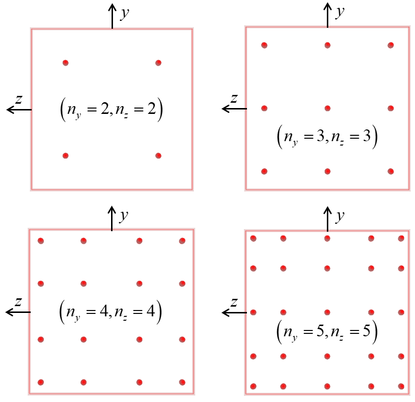
Figure 1: Beam element with rectangular cross section showing different integration-point layouts.
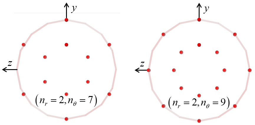
Figure 2: Beam element with circular cross section showing different integration-point layouts.
| Was this helpful? ... | Itasca Software © 2024, Itasca | Updated: Nov 12, 2025 |
